|
A Novel Approach to an Ignition Box For Old Jump Spark Engines - by Miro Forest This
article was inspired by my need to make a reliable ignition box that would fire
my 1911 Gray 1 cylinder, 2-cycle , marine engine. The design is not new –
simply put, it was how I did it with the tools and materials at hand. I
wanted to make sure that whatever I made, was reliable, since about 80% of
problems with old engines are electrical, even though the electrical system is a
very model of simplicity. The
parts I used for the critical bits, were from modern ignition systems – a 12 v
ignition coil, and a set of points from a lawn mower engine that had died. The
12 v ignition coil was “recycled” from the local dump and was rescued off a
worn out outboard motor. Actually, it was a 2 cylinder, so I got 2 coils. The
key thing to understand about this ignition box is that it is part electrical
and part mechanical. Both parts have to work properly for the spark to be
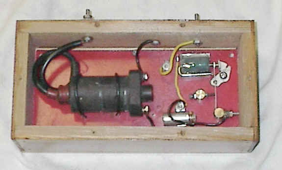
reliable. There’s a diagrammatic layout of my ignition box.
The
dashed lines are the low voltage connections. The box was designed to operate
satisfactorily on a 6 v dc dry cell. The heavy black line from the 12 v ignition
coil is the high voltage wire. Essentially
what happens is that the points are closed when the 6V is applied to the primary
circuit. This causes a flow of current through the buzz coil, creating a
magnetic field. This magnetic field attracts the spring arm of the points,
causing the points to open. The current stops flowing, the magnetic field in the
buzz coil stops, the spring on the arm of the points (mechanically) causes the
points to close. When the points close, it causes a current to flow etc etc and
repeats . . and . . .
buzzes. It is the interruptions in the current flow, that induces the
high voltage from the primary winding of the 12 v ignition coil to the high
voltage secondary winding . I get open air arcs at least 3/8 in
long. When connected to a spark plug with a .035 gap, there is a bright
blue fire. WATCH
OUT though – the high voltage from this box will give you a really good
sting if you touch it. – You’ve been warned! The
buzz coil is about 1½ in. long and has about 300 turns of No. 20 wire (enamel
insulation). The heavy line is a 3/16 dia.
steel U shape, so that I , in effect , have a horseshoe electromagnet
when the current is flowing though the coil. The U shaped steel piece helps
confine and concentrate the magnetic field so here is a strong pull on the
spring arm of the points.. The buzz coil is epoxied to a bed ( an aluminum half
round channel) which is itself held to the base with a small bolt. The
base is a sheet of 1/16 in thick stiff plastic sheet. The
pressure adjuster is a brass ( non-magnetic) post, threaded to hold a 10 x 32
screw and a lock nut, which allows the pressure on the points to be “tuned”.
The
points ( from the old lawn mower engine) consisted
of the stationary part and a spring mounted part. I straightened the spring, but
I found that the arm was too long and like any pendulum, vibrated at too low a
frequency. The pressure adjuster shortens the pendulum arm, and makes the points
vibrate at a higher frequency . The sound the buzzing makes is about Middle C (
440 cps). With the longer pendulum arm, the frequency was much lower
and the contact was less reliable ( less mechanical pressure ). I
found that the system worked much better when I added the capacitor
connected across the points. The capacitor was from the same dead lawn mower
engine. As
for tuning the thing, I found that there was a sort of optimum pressure
of the adjuster which could be determined by measuring the current (
about 275 - 300 mA), listening to the buzzing, and listening to the noise that
the spark made jumping across the gap in the spark plug. You’ll see, hear and
feel the variation. One you have the optimum point, you lock down the pressure
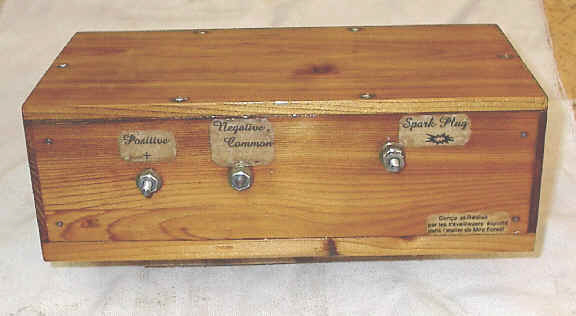
adjuster’s lock nut. I then made a cedar wooden box for the guts, connected the 6V wiring and the high voltage to small bolts that allow connections to the outside battery and plug, varnished the box and , voila – an ignition box for my Gray engine !
Miro Forest |
|
Home
| Discussion Board | History
| Technical | Links
| Store | About
Us | Email |