| Author |
Message |
    
Searcher
Senior Member
Username: searcher
Post Number: 124
Registered: 10-2004
| | Posted on Sunday, July 02, 2006 - 10:49 pm: | 


|
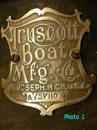
The engine portion of this Truscott does not look like any other Truscott I have seen. The first question that came to mind is whether the tag on this two cycle is original to the engine. All Truscott tags I have seen bear a serial number. The notation on this engine's tag (Photo 1) is A75V110. I take that to mean 7.5 amps and 110 volts. That would tend to indicate the tag does in fact belong on this engine-dynamo combination.
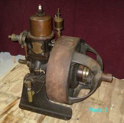
The Big Yellow Book depicts two Engberg engine-dynamos at the top of Page 153. The illustration on the left is of a four cycle engine-dynamo with many of the same characteristics as the two cycle engine-dynamo pictured here. The illustration on the right mentions that Engberg also made small two cycle dynamos.
Engberg and Truscott were both located at St. Joseph, Michigan, and in business at the same time. My guess is that Truscott had an order for a boat and that order included a request for a light plant. Truscott may have retagged an Engberg so that the hull and equipment all bore shiny brass Truscott tags. If these assumptions are anywhere near correct, did Engberg build the dynamo only and somebody else build the engine portion to Engberg's design?
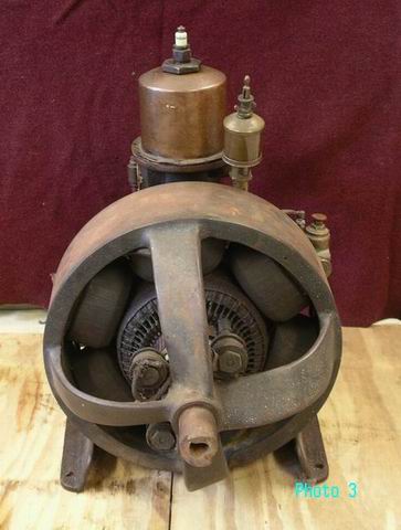
A most curious aspect of this outfit is the manner in which the dynamo functions (the Engberg on the left on Page 153 of the BYB also functions the same way). The elongated crankshaft extends through the center of the fixed stator. The flywheel (heavy iron ring) seen in the photos is attached by 4 spokes to that extended crankshaft. The field coils are bolted to the inside of the flywheel. The flywheel and field coils cantilever back over the fixed stator. So, when this engine-dynamo is in operation, that whole flywheel bearing the field coils is spinning away at 500 rpm or so around the fixed stator. The spokes are twisted and act as fan blades to pull air into the dynamo. Maintaining this little beast in an enclosed space in the bottom of a rolling boat must have been exciting given the exposed rotating dynamo on one end and the exposed rotating pump drive on the other end.
I would like to restore this engine-dynamo to working condition (but not repaint it). I have a number of questions related to restoration.
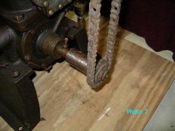
First off, can anyone provide me with photos or a description of the drive from the crankshaft to the water pump? Photo 7 depicts the skip tooth chain and sprocket from a hand crank engine starter temporarily slid onto the crankshaft. Does this look like a reasonable solution? I also have the skip tooth chain off the magneto drive from an early marine engine along with one matching sprocket. I discovered that the small bicycle sprockets from the teens and 20's are a perfect fit with that mag chain and the sprockets could be adapted to the pump and crankshaft. Would that be a better solution? Are there any suppliers left that carry skip tooth sprockets where I might find a match to the one sprocket that survived with the magneto drive chain?
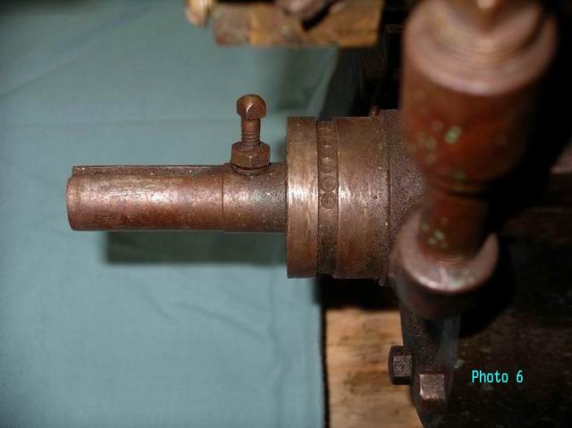
The entire timing device is missing except for the contact stud on the crankshaft visible in Photo 6. The machined groove on the projecting part of the crankcase in Photo 6 indicates there was a timing device and the groove acted as a guide for that timing device. Note the 6 dimples in the groove. The 6 dimples are repeated on the bottom side of the groove. Were they for a detent of some sort? Would the timing device have resembled that found on many of the Detroit family of engines?
The crank end (See photo 3) will turn in only one direction by design. Consequently, I assume that the dynamo was made to put out power turning in that one direction only. There must have been some kind of stop on the timing device to prevent starting the engine by rocking the flywheel backwards?
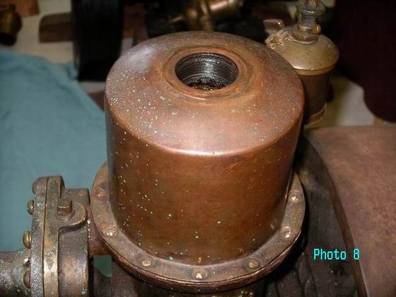
Photo 8 shows the copper water jacket with the plug adapter removed. The heads of all the brass screws holding the copper water jacket down popped off as soon as threatened by a screwdriver. I would like to remove the water jacket so it does not get damaged when I drill out the broken brass screws. After having twisted off the tops of all the brass screws and removing the plug in the top, I thought the water jacket would simply pop right off. However, it still feels as solid in place as it did before the screws and plug were removed. Is there something else I need to know about removing that jacket?
The mixing valve is a ¾" Monarch. A 1" pipe thread opening in the crankcase was bushed down to ¾" to accept the Monarch. Could the Monarch be original? If not, I have a 1" Lunkenheimer 'nonpariel' mixer. Would the 1" Lunkenheimer be a more likely candidate?
I had an electrician test the dynamo but he was rather baffled by it. He did conclude that one of the field coils has a break in a wire somewhere. Is there anybody left that can rewind one of those coils?
Can someone help me date this?
I would really appreciate any and all comments and help with this one. This is the first marine related engine I found and it is of more personal interest than some of the others I acquired later.
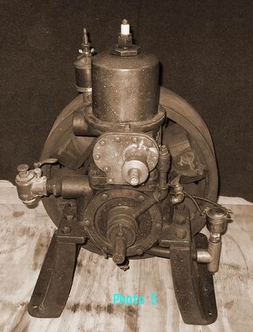
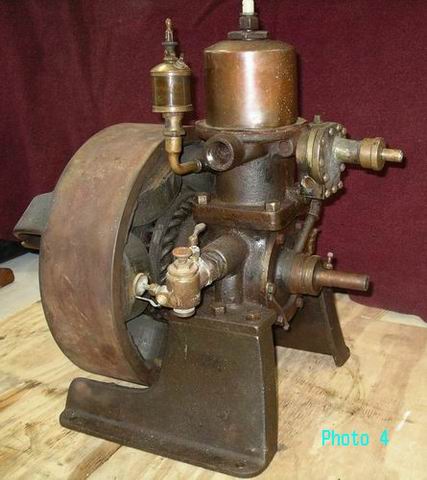
 |
    
Peter Ogborne
Senior Member
Username: peterogborne
Post Number: 150
Registered: 09-2002
| | Posted on Monday, July 03, 2006 - 12:23 am: | 


|
Searcher........what a beautiful little unit. Sorry I can only offer you envy.
Great to see it saved and being restored |
    
Searcher
Senior Member
Username: searcher
Post Number: 125
Registered: 10-2004
| | Posted on Monday, July 03, 2006 - 07:35 am: | 


|
Thanks. Beginners luck, haven't found anything as neat since. Reminds me of my first time candle pin bowling, strike on the very first roll, there was quite a few rolls of the ball before I got another one though. |
    
Tom Stranko
Senior Member
Username: thomas
Post Number: 227
Registered: 07-2002

| | Posted on Friday, August 25, 2006 - 07:36 pm: | 


|
I have an 8-1/2 X 11 1906-07 Truscott catalogue.
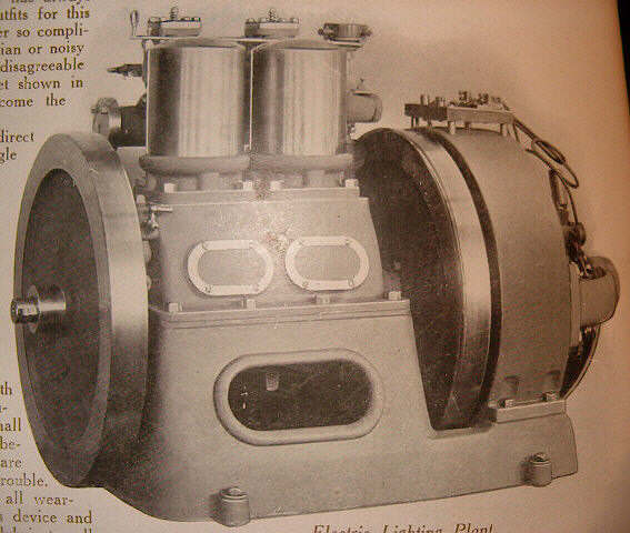
On P68 they talk about one and two cylinder Truscott electric lighting plants.They list two 4 cycle and two 2 cycle units; a single or a twin cylinder in each style. Price was $325 to $700 (my guess is that would be the average months salary in 1907)
This is your engine manufacturer. Same cylinders.
Picture of the 2 cylinder 4 cycle attached (see the tops of the intake valve chests on reverse side) I can email a better quality pic if you email back. |
    
Tom Stranko
Senior Member
Username: thomas
Post Number: 228
Registered: 07-2002

| | Posted on Friday, August 25, 2006 - 07:37 pm: | 


|
 |
    
Roger DiRuscio
Senior Member
Username: solarrog
Post Number: 175
Registered: 03-2002

| | Posted on Friday, August 25, 2006 - 07:57 pm: | 


|
What a great find, Im also a generator collector, but I have never seen or heard of this unit, You have my envy also |
    
Tom Stranko
Senior Member
Username: thomas
Post Number: 237
Registered: 07-2002

| | Posted on Sunday, August 27, 2006 - 02:16 pm: | 


|
Searcher,
Having read your text I agree that the mixer on the engine looks small; probably the size to match the fitting would be right. (also the needle adjust knob would not be next to the spinning flywheel)
Can't help much on the W pump drive. Chain would work but I would have thought there was a way for the engine manuf. to put the pump closer to the C/S. Is it possible there was a magneto between the pump and the crankshaft? That timer trip pin
is interesting. I guess you will have to fabricate something until or unless you get a diagram of the Engberg layout. VERY NICE unit.
Good luck. (try the "Smokestacks" (old hit&miss engine chat ) for Engberg help)
Tom |
    
Tom Stranko
Senior Member
Username: thomas
Post Number: 238
Registered: 07-2002

| | Posted on Sunday, August 27, 2006 - 02:21 pm: | 


|
I forgot to mention that you might try an electric motor repair shop to check out the coils and windings; I'm not sure if a (house wiring etc. ) electrician would have that specialized knowledge right on the top of his head. (no offense to the electricians)
T |
    
Searcher
Senior Member
Username: searcher
Post Number: 135
Registered: 10-2004
| | Posted on Tuesday, August 29, 2006 - 12:53 am: | 


|
Tom,
Thanks for responding. There doesn't seem to be room enough to put a magneto in there but anything is possible. The engine castings were clearly designed to mount that specific water pump despite having an extended drive shaft. The drive shaft of the water pump actually extends out a bit further than the crankshaft. I am convinced that water pump is original to the engine. I would agree that the whole arrangement has a gangly look if it was hooked up as I propose. I am going to wait awhile before trying to make something up in hopes somebody will eventually respond with photos of another one.
There was a makeshift timing device on the unit when I got it. After looking at a bunch of timing devices at Mystic a week ago, I am beginning to have some inkling of what the original probably looked like. I now realize that the shaped and drilled block of old red insulating material that was incorporated into the makeshift timing device was probably a part of the original timer. That's a help.
I will contact a motor repair shop as you suggest to see what they can do. The electrician that looked at the unit made a call to an outfit that he though might rewind such things. They told him he was nuts for having anything to do with it because of liability issues!!!!
Thnaks for the comment Roger. |
    
Searcher
Senior Member
Username: searcher
Post Number: 136
Registered: 10-2004
| | Posted on Tuesday, August 29, 2006 - 09:01 am: | 


|
Roger,
Would you venture a guess as to when this motor/dynamo was built? |
    
Roger DiRuscio
Senior Member
Username: solarrog
Post Number: 176
Registered: 03-2002

| | Posted on Tuesday, August 29, 2006 - 01:59 pm: | 


|
My guess would have to be a range between 1915 to 1925. The copper water jackets showed up by several manufactors about 1914 and disappeared almost entirely by the middle twenties
I would put a meter on the winding before messing with them, the insulation will be fragile
The water pump looks like a gear pump. I have seen those used one many different manufactors engines |
    
Searcher
Senior Member
Username: searcher
Post Number: 587
Registered: 10-2004
| | Posted on Sunday, November 24, 2013 - 10:10 pm: | 


|
As Paul Harvey would say - �The rest of the story�.
Since my original posting of this Truscott dynamo on OME in July 2006, I have read, bought, and traded, for anything I could find on Truscott hoping eventually I would find an ad or photo depicting one of them. Over time, I acquired four references to the dynamo and copies are attached herein.
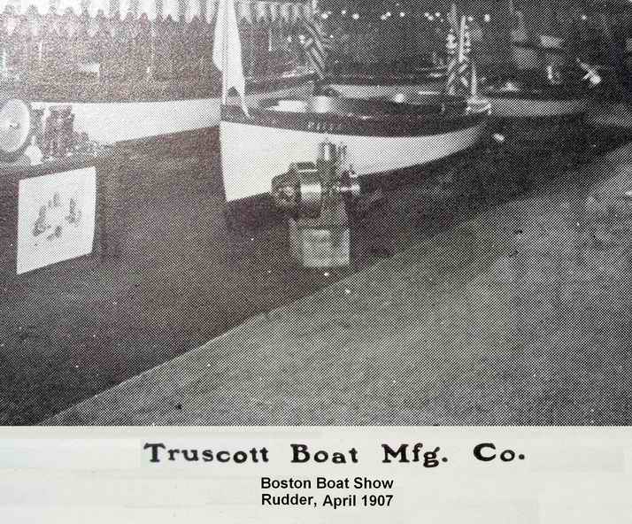
The first depiction of a Truscott dynamo was brought to my attention by an observant marine engine collector in Maine. It was a photo in The Rudder magazine of Truscott�s 1907 Boston boat show layout. The image is rather grainy but it clearly depicts one of these dynamos.
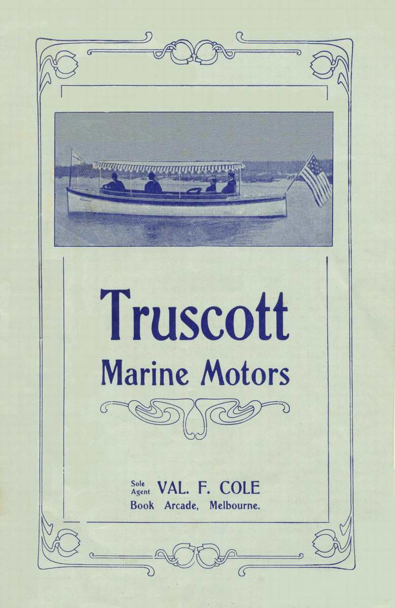
The next bit of information came via eBay and an undated sales brochure printed in Australia, a tantalizing piece of the puzzle because of a reference to the Truscott dynamos. Unfortunately, there were no illustrations.
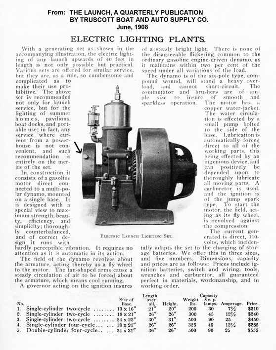
Then I acquired the June 1908 issue of the Truscott Boat and Auto Supply Co. quarterly publication The Launch. Lo and behold, finally, there was the dynamo and a description of its features. That was quite exciting. While it didn�t answer all my questions, I now knew that the dynamo was throttle governed, used a float feed carburetor, was rated at 30 lights of eight candle power each, and was designated as a No. 1, the smallest size Truscott dynamo. What looked like a counter balancing flywheel on the front of the engine is described as being part of the ignition/governor system and not a flywheel. It does appear to be quite light in comparison to a true flywheel.
Finally, I found a copy of the 1907 Truscott Boat and Auto Supply Co. catalog. That also has an illustration and text describing the dynamos.
The dynamos depicted in the 1907 Truscott Boston Boat Show exhibit, the 1907 Truscott Boat and Auto Supply Co. catalog, and the 1908 issue of The Launch are identical. The dynamo posted in this thread has some features that are not seen on the three dynamos illustrated in the publications.
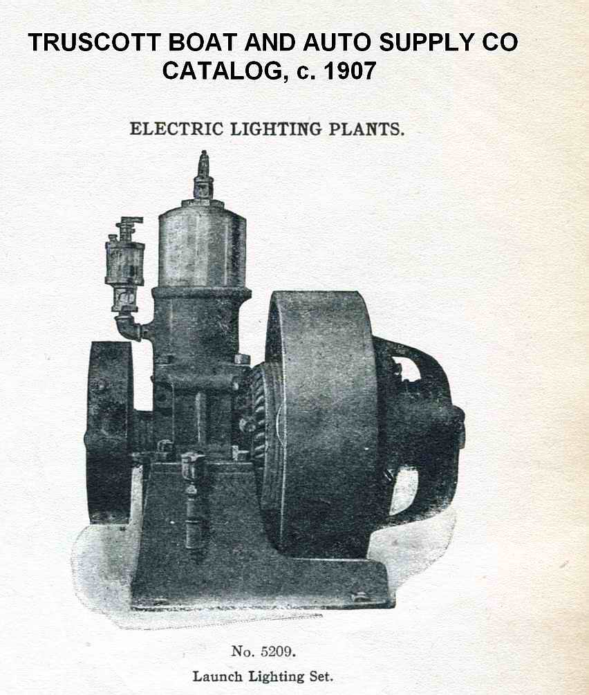
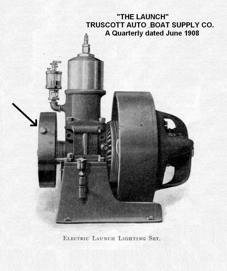
A. The shaft on the dynamo posted in this thread extends out as much as three inches and has lugs on the end for seating a crank. That shaft would present a very high risk for grabbing loose clothing. The three dynamos in the illustrations either do not have that extended shaft, or have a much shortened version of it that is not visible. I put an arrow on a couple of the illustrations pointing to a knob on the governor housing. Maybe, the crank arrangement was abandoned and replaced by a pull out handle. A very definite safety improvement if true.
B. Servicing the oil cup on the dynamo in this post would have been hazardous because it was in an awkward location very close to the revolving field coils. The oil cup on the three dynamos in the illustrations appears on the side of the block away from the field coils, a safety improvement.
C. The water pump on the dynamo in this post bolted onto the block on the side facing away from the field coils. It was either chain driven off a sprocket on the crankshaft, belt driven off the governor housing, or friction driven off the governor housing. No matter, a chain, belt, or friction drive in that position presented a serious hazard. The water pump cannot be seen on the three dynamos in the illustrations because it is bolted onto the side of the engine (per Truscott literature), a definite safety improvement. Truscott�s description of the pump on the illustrated dynamos would leave one to believe that it was not chain or belt driven.
D. Based on the above changes to the design, all of which led to greater safety, my guess is that the dynamo posted in this thread is probably an early version, c.1906.
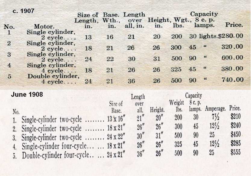
Truscott�s 1907 catalog and the 1908 copy of The Launch both provide a price list for the various Truscott dynamos. There was a remarkable drop in the price of these dynamos between 1907 and 1908. Perhaps sales were very poor for these strange contrivances and Truscott was trying to build a market? Maybe Truscott was clearing inventory and getting out of the dynamo business?
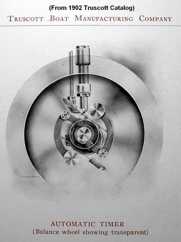
Truscott had an interesting arrangement on their early marine engines where a centrifugal device automatically advanced or retarded the spark. I�m wondering if an adaptation of this advance/retard design was used as the basis for the governor on the dynamo?
 |
    
J.B. Castagnos
Senior Member
Username: jb_castagnos
Post Number: 844
Registered: 07-2002

| | Posted on Monday, November 25, 2013 - 07:28 pm: | 


|
The governor appears to control timing, retarding to limit speed. It looks like it is rotating the flywheel, the inner pivots are on a ring keyed to the shaft. The cutaway also shows a piston water pump, eccentric and strap, not shown on any of the engines. |
    
Tom Stranko
Senior Member
Username: thomas
Post Number: 357
Registered: 07-2002

| | Posted on Monday, November 25, 2013 - 07:53 pm: | 


|
I had a 1903 Truscott 1 cylinder 2 cycle. The "automatic timer" basically put the M&B at a TDC or possibly slightly retarded setting at start time and after starting it pretty quickly put the M&B in full advance. This is good if you have a fixed full pitch prop connected but it was killing me trying to run slow at an old engine show. I wired the centrifugal arm in the retard position and I made a coaxial offset cam thing that I could turn to move the igniter trip closer to the mechanism (retard) or back away from the mechanism (advance). This worked very well for all the years I wanted to run it no-load at a show. |
    
Searcher
Senior Member
Username: searcher
Post Number: 588
Registered: 10-2004
| | Posted on Monday, November 25, 2013 - 09:05 pm: | 


|
I have difficulty visualizing two dimensional drawings like the 1902 cut above in three dimensions. The only way I will be able to understand how this automatic timing device works is to take the flywheel off my Truscott marine engine (similar to the one Tom had) and see first hand if there was a possibility Truscott could have adapted the timing design to throttle a carburetor.
The automatic timer and piston pump depicted in the above 1902 cut from the Truscott catalog is on a Truscott single cylinder, 2 cycle, marine engine and not on one of the dynamos. I should have made note of that.
My Truscott dynamo has a brass gear pump on the front that was chain, belt, or friction driven. The little information I have gleaned from Truscott's descriptions indicates the dynamos in these cuts have pumps mounted on the side that are not chain or belt driven. Hopefully, somebody will come up with one that has the side mounted pump. |
    
J.B. Castagnos
Senior Member
Username: jb_castagnos
Post Number: 845
Registered: 07-2002

| | Posted on Tuesday, November 26, 2013 - 08:39 am: | 


|
That must be the ignitor link hooked to the water pump, that would make more sense, the weights are advancing the pump eccentric. |


