| Author |
Message |
    
andrew
Moderator
Username: andrew
Post Number: 1056
Registered: 11-2001

| | Posted on Tuesday, February 22, 2005 - 10:26 am: | 


|
The following was sent to me by email by Bruce Wright.
I sure there will be some responses. Is this serial number on Dick Day's list?
We sell the manual for the Palmer ZR if you need it.
quote:Sirs:
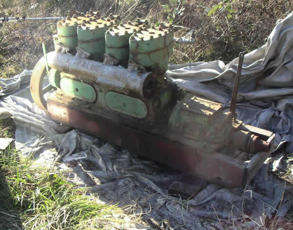
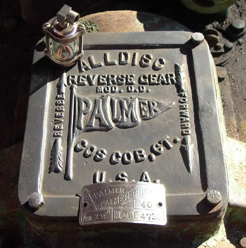
We are cleaning up an old Palmer. Here is a photo of engine and gear tag.
Can you tell us anything about this engine? Year of manufacture? Any specific sites for info?
Many thanks
Bruce C. Wright
[email protected]
Skyline Marine Owners Assn. 17 - V. P.
Anacortes WA


|
    
andrew
Moderator
Username: andrew
Post Number: 1057
Registered: 11-2001

| | Posted on Tuesday, February 22, 2005 - 10:32 am: | 


|
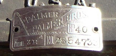
Enlarged nameplate:
 |
    
richardday
Senior Member
Username: richardday
Post Number: 364
Registered: 11-2003

| | Posted on Tuesday, February 22, 2005 - 09:05 pm: | 


|
I just spent about an hour trying to give these chaps a quick lesson on the ZR series and proceeded to lose it all some how. I suggested that they purchase from Andrew the ZR manual and the Palmer Handbook if they are to stay out of trouble if it has an Atwater Kent ignition system. Can not tell as we don't have a starboard side view.
I think the serial number is 2854733 which would make it 1933.
There are a couple of points about this engine. I think it has a three bolt exhaust manifold. The change to three bolt took place in 1938. The cylinders appear to have only two bolt flanges which suggests they might be original to 1933. Either manifold will work and it was a common practice to replace cylinders or manifold without worrying about the two bolt three bolt configuration as they were backward compatable. They went to three bolts to stop the leakage that would develope if the exhaust pipe wasn't properly supported. The addition of the top stud eliminated the water leaks at the upper side of the gasket.
This engine is a true left that is it runs counter clockwise facing the flywheel looking aft. The lever on the forward port side is a compression release that you push aft to start and immeadiatly pull forward to run. The plates on top of the starboard side of the cylinder heads are covers over the steam/air trap. This feature insures that any water or steam is forced up and then down and out the discharge to the water heated intake manifold. The discharge from the intake manifold was typically routed 3/4 down the exhaust pipe to cool it and 1/4 over the side as a "tell-tail" The correct reverse gear vent was a short (approx 1-1/2" long)pipe nipple with a 90 degree el.
The reverse gear is not lubricated from the engine crankcase. Use SAE 30 non-detergent motor oil not heavier. Level should be about 1" below shaft at aft end of reverse gear. Don't overfill.
Normally there would be an air oven aft of the exhaust manifold with a flexible metal tube to the intake of the carburetor. Oil filters were not added until about 1937. A 3/4" PCV flexible tube was routed to the air intake of the carburetor by connecting it to the air pipe from the oven. There should be 3/4" NPT street EL between the number 3 and 4 cylinder on the starboard side. This was connected to the PCV tube. The intake air inlet to the crankcase was a mushroom shaped filler pipe which acted as an oil fill funnel and air intake. It screwed into the oil fill 3/4"NPT next to the compression release. The brass cap over the left hand thread puller nut was to keep one from catching their pant cuff in the hub of the flywheel when "Stomping" on the flywheel against compression on a retarded spark. The engine would backfire and start running counterclockwise. Many watermen didn't mess with choking the engine. They had a gasoline priming bottle and would prime each cylinder and retard the spark and "Stomp" on the spokes. They hated the disk flywheels and often if a new engine was delived the first thing they would do is replace the new disk flywheel with an old spoked flywheel.
The ZR series engines can be timed to run either as true rights or true lefts. The normal practice was the true left was the port engine as this put the mag and carburetor on the inboard side of the engine. In a true right the exhaust is on the Starboard side and the mag and carburetor are on the inboard side which makes it easy to service in a twin screw operation. The compression release would be on the outboard side of each engine in the twin screw appication.
The ZR-4 is rated a 40 Hsp at 800 RPM. Weight 1300 lbs. Swung a 24" by 18" prop. 5-1/2" bore 6" stroke.
There are at least 4 known ZR-4 engines known to exist. This engine would make that 5. The last ZR-4 was made in 1957 and is still operating on a lake in CT. Around the Chesapeake Bay the ZR-1 was called the Cadilac of the workboat engines by the watermen. The last operating ZR-1 was taken out of the water in 2001. It has been preserved and will be back as soon as a little cosmetic work is accomplished. Hope this helps in your work but don't forget yours is a left handed engine. PS.
Beware the left hand thread puller nut is probably set up for right hand 1/2" 12 Thd not repeat not 13 thd. Ray Palmer never agreed with the 1/2" 13 thd standard, Don't try to tap the 12 thread with a 13 tap as all you will do is destroy the 12THD and the 13 THD. All ZR series engines use left hand puller nuts to hold the flywheel in place regardless of whether they are true rights or true lefts. There is no intent that the holes in the puller nut line up with the threaded holes in the hub as a means to lock the puller nut so don't over stress the threads trying to line the holes up so you can lock the puller nut in place. The factory never made any attempt to machine these parts to line up and the fact an occasional one will isn't a license to try to force it on other units. |
    
andrew
Moderator
Username: andrew
Post Number: 1062
Registered: 11-2001

| | Posted on Wednesday, February 23, 2005 - 09:20 am: | 


|
Dick,
Thanks for providing so much info for them!
I just shipped him the ZR manual.
Sorry you lost your first attempt at a reply, one thing you (or anyone) could consider if you are writing a long reply is to write it first in Notepad, WordPad, Word, or any word processor on your computer, save it periodically... and when you are done - copy and paste it into here. Special fonts and formatting won't work, but it will allow you to save and edit the work prior to posting. On the MarineEngine.com discussion board we have a person that posts regularly (over 3000 posts) and he saves responses and a text file and just pastes them in when required...
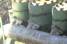
Here is a closeup of the manifold from the higher resolution photo that Bruce sent me.
 |
    
richardday
Senior Member
Username: richardday
Post Number: 366
Registered: 11-2003

| | Posted on Wednesday, February 23, 2005 - 09:34 am: | 


|
Thanks for the tips Andrew. Will see if I can manage to do that notepad bit. Probably beyond my pay grade or age group or something.
Does that photo look like the top of the flanges have no studs or nuts? it does to me. Did they have any photos of the starboard side? |
    
andrew
Moderator
Username: andrew
Post Number: 1063
Registered: 11-2001

| | Posted on Wednesday, February 23, 2005 - 12:18 pm: | 


|
Dick,
Those were the only two pictures he sent. I zoomed in to get the nameplate detail and the manifold detail. I have tried zooming in more on the manifold but it gets blurred when I do so.
Hopefully Bruce will respond with some more details and photos.
Bruce, you can just post your comments in the message box below... |


