| Author |
Message |
    
narrabay2
Senior Member
Username: narrabay2
Post Number: 165
Registered: 10-2019
| | Posted on Friday, April 16, 2021 - 05:15 pm: | 


|
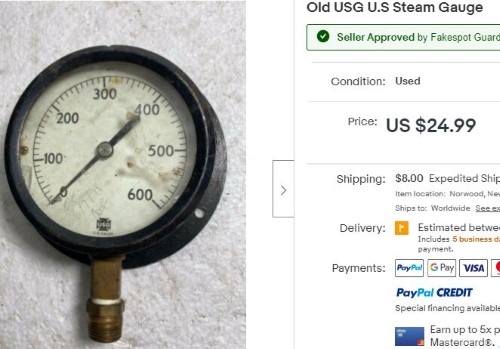
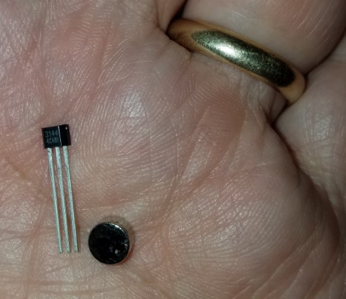
Well, this would make three major projects that are "in process" - cyl head for YT, repro-Dispro, and now this. I found a great candidate for a old school RPM gauge. And I checked with an engineer friend and no problem to do it the way I envision. Parts ordered. It's really the perfect RPM dial range for this as even with an 800 RPM "red line" I dont see the YT-1 getting past 600 when in use (especially since it seems a little over-propped). So, I'll update this thread as it goes along. If the approach works, others can duplicate it to get an old school steam gauge tach working with no alteration to the engine. There will only be one brown cloth wire from the bottom fitting to the lower engine bed next to the flywheel...
Miro will probably figure out from the clues here exactly how this will be done! 
 |
    
narrabay2
Senior Member
Username: narrabay2
Post Number: 169
Registered: 10-2019
| | Posted on Monday, April 26, 2021 - 09:36 pm: | 


|
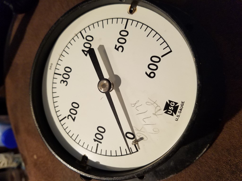
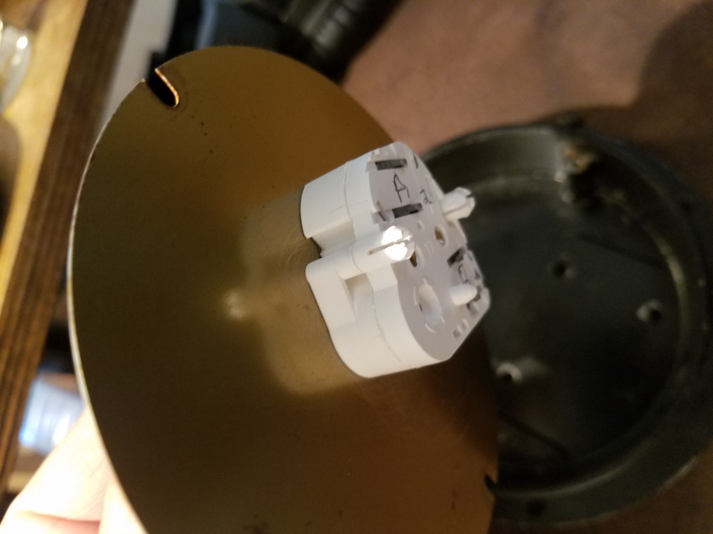
with help from a C++ programmer, ran a test today using an arduino nano and a similar motor responds. mounted the motor and drilled and pressed the original pointer onto the shaft. progress. the electrics should all fit inside the steam gauge. a sensor will be down at the flywheel.
 |
    
ned_l
Senior Member
Username: ned_l
Post Number: 229
Registered: 08-2012
| | Posted on Monday, May 03, 2021 - 12:21 pm: | 


|
This is looking interesting! |
    
narrabay2
Senior Member
Username: narrabay2
Post Number: 170
Registered: 10-2019
| | Posted on Tuesday, May 04, 2021 - 12:13 pm: | 


|
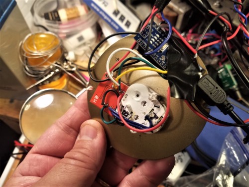
Hi Ned, some programmer friends are assisting. I have the arduino nano and driver soldered up to a Saturn car speedometer motor, and a program for just this application from the internet somewhat working. The experts will have that sorted soon. There are lots of these on youtube, most dont show the source code though. The flywheel will have a small magnet on the back and a tiny hall effect sensor on a bracket inside the engine bed will read it when it comes around.
When I saw the dial shows the exact numbers for the YT RPM, just had to make it into a tachometer...
 |
    
narrabay2
Senior Member
Username: narrabay2
Post Number: 175
Registered: 10-2019
| | Posted on Sunday, May 23, 2021 - 01:44 am: | 


|
It's now working in beta. 15 rpm resolution, next is to reduce that so the needle moves less and more smoothly...
https://youtu.be/5_xJwbFjQ34 |
    
narrabay2
Senior Member
Username: narrabay2
Post Number: 176
Registered: 10-2019
| | Posted on Monday, May 24, 2021 - 11:43 pm: | 


|
It's back together! Epoxied the electronics to the back of the dial. Supposedly heat can remove. Hope to never need to try that...
Now to figure out waterproofing. There's silicone coatings that can be painted on circuit boards I may try, in addition to trying to seal the instrument casing itself.
Video:
https://youtu.be/OJJ_6bAHG10 |
    
narrabay2
Senior Member
Username: narrabay2
Post Number: 177
Registered: 10-2019
| | Posted on Tuesday, May 25, 2021 - 01:20 am: | 


|
and another video tape, this time mounted to my little instrument panel I made this week out of a piece of pine... showing changing the motor speed and how the tachometer reacts... checked with a handheld digital tach and its very accurate everywhere on the dial, within 10rpm or better...
this is very exciting so please make sure you're sitting down or holding onto something 
https://youtu.be/sa9jJstORYk |
    
dick
Advanced Member
Username: dick
Post Number: 44
Registered: 07-2004
| | Posted on Tuesday, May 25, 2021 - 05:13 am: | 


|
Terrific |
    
narrabay2
Senior Member
Username: narrabay2
Post Number: 179
Registered: 10-2019
| | Posted on Sunday, May 30, 2021 - 12:16 am: | 


|
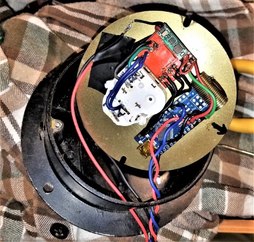
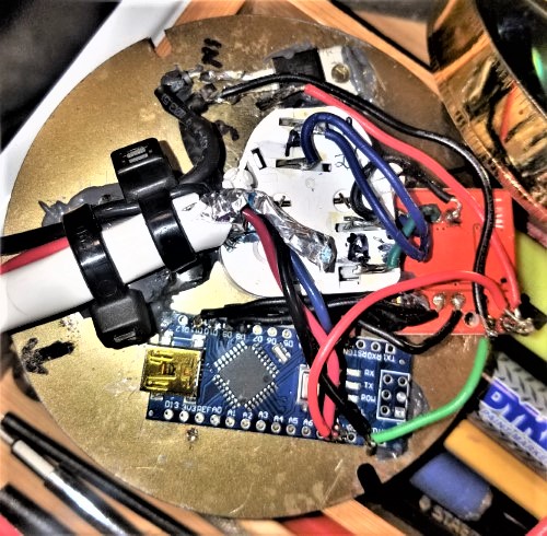
and this is the inside. components glued onto back of the dial with jb weld 1 minute epoxy, wires neatened up. most key thing will be sealing it all up water tite
 |
    
narrabay2
Senior Member
Username: narrabay2
Post Number: 182
Registered: 10-2019
| | Posted on Saturday, June 12, 2021 - 12:02 am: | 


|
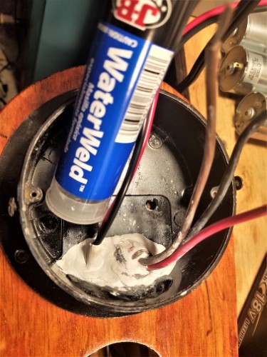
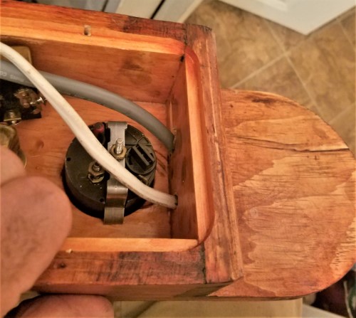
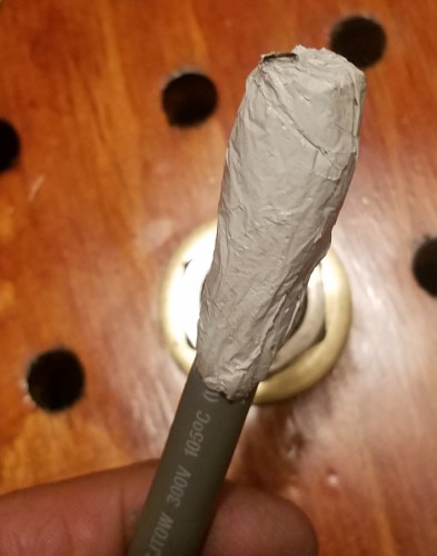
Couple pictures on how I sealed the unit wire entries. The glass will be sealed by bedding around the edge with clear silicone. The 3-wire going to the flywheel pickup has the same "JB waterweld" epoxy paste. That can be sanded and dipped in paint.
 |
    
narrabay2
Senior Member
Username: narrabay2
Post Number: 183
Registered: 10-2019
| | Posted on Sunday, June 20, 2021 - 12:27 am: | 


|
Just a quick update. The tach works great (perfectly) on the bench, but in the boat it gets interfered with and the needle jumps. And its not just the obvious culprit buzz box coil because I tested without that and its very sensitive to anything electrical.
But others have made these for gasoline spark engines and those work (some on youtube), so just need to shield it or isolate it or whatever. So it's a little setback, but we'll get it solved...
On the plus side, the engine starts instantly, runs smooth and quiet, and runs really well, pumps water, everything good there and will be taking her out for a ride soon. |
    
narrabay2
Senior Member
Username: narrabay2
Post Number: 184
Registered: 10-2019
| | Posted on Sunday, June 20, 2021 - 12:28 am: | 


|
... |
    
narrabay2
Senior Member
Username: narrabay2
Post Number: 186
Registered: 10-2019
| | Posted on Tuesday, June 22, 2021 - 12:43 pm: | 


|
Ok narrowed it down by snipping the remaining 2" of digital input lead on the little nano computer and it settled down.
So it is the input only it would seem. This makes sense since the red led that blinks whenever there is a pulse from the magnet detector, was flickering so it was getting phantom pulses. Clipped the lead and its quiet. So the noise was getting in to that little wire acting as an antenna. I was concerned that the EMI was pervading the whole setup and would be impossible to shield, but this test seems to show that's not the case.
all I have to do is shield that pickup wire and according to my expert friend, add a few capacitors across the hall effect sensor leads and at the input point and try it.
The shielded marine "signal wire" has arrived (not cheap!) and the .01uF capacitors coming tomorrow (those were cheap), and we'll see.
Here's the new test. It did go full scale after the restart of the Palmer, but only once and it settled right down again.
I'm not an electronics expert but thankfully getting some good advice from a friend who is.
https://youtu.be/xBbxFYfLFZI |
    
narrabay2
Senior Member
Username: narrabay2
Post Number: 187
Registered: 10-2019
| | Posted on Saturday, June 26, 2021 - 10:17 pm: | 


|
OK, it now works! A little jumpy but expecting to settle that down with software changes.
Potted the sensor in a copper tube and JB Weld.
Video of it installed and working...
https://youtu.be/DcPFqmtFaAQ |
    
ernie
Senior Member
Username: ernie
Post Number: 2637
Registered: 01-2002

| | Posted on Sunday, June 27, 2021 - 08:30 am: | 


|
Is it related to the refresh rate or buffering? Compared to the little motor you tested it with the YT has a long time from pulse to pulse. If you look at the video the tack is pulsing in sync with the water pump eccentric. Yea I know a revolution is a revolution but still???
Did it work OK at 200 RPM ish on the test bench? |
    
narrabay2
Senior Member
Username: narrabay2
Post Number: 188
Registered: 10-2019
| | Posted on Sunday, June 27, 2021 - 01:46 pm: | 


|
hi ernie thats very possible but theres a couple things, one, the software my programmer wrote had a 15 rpm resolution and if the engine was straddling the edge of one of those increments, the needle would move to the next 15 rpm reading and back. we reduced that to 7 rpm and could not get better than that because this has a non-micro-step driver board. I can upgrade that and pay from the program changes, but not until we enjoy the boat.
I am *pretty sure* that when I fried the Arduino Nano the other day with reverse polarity by accident, I loaded the 7rpm latest software version into the new nano. But it sure looks like the 15 used to look! there is a 7805 voltage regulator chip epoxied to the back of the dial, and when that saw reverse 12v it let that right through and the nano was toast. It now has a diode to prevent that again.
The glass and wires entry is all sealed now with clear silicone and it works, so going to put off checking the software version or other improvements until we can enjoy the boat a few times. the biggest worry now is moisture, but all these parts are ridiculously cheap in case something happens. we're talking like $10 bucks or so for everything in there.
after that, I have already asked the programmer for a estimate to write in micro stepping and Mike T suggested asking about an "averaging" formula to steady out the readings. I'm pretty confident that this can be as steady as the one in our cars with those changes. Another additional option might be to use 2 magnets and make the simple coding change for that.
as to the readings, I was surprised how easy it goes pretty high. for example it cranks at 400 rpm!!! I could take out the spark plug and use that as silent running mode (kidding!)
 |
    
narrabay2
Senior Member
Username: narrabay2
Post Number: 193
Registered: 10-2019
| | Posted on Saturday, July 31, 2021 - 07:04 pm: | 


|
Just realized I never posted a success video to finish this development thread. Here it is and this was the last time the engine was running right! But the tacho is nice to have as I chase an erratic idling issue...
https://youtu.be/1WdO9uP9Tpc
. |
    
narrabay2
Senior Member
Username: narrabay2
Post Number: 198
Registered: 10-2019
| | Posted on Monday, August 16, 2021 - 03:21 pm: | 


|
Tach working as designed so far, many hours on it. It is still a little jumpy (by about 20rpm or less) due to not using a micro-step driver board but gives accurate and useful speed data up to about 700 rpm.
So, for that reason and the thin steel glass-retainer bezel which can rust, V 2.0 is in the works!
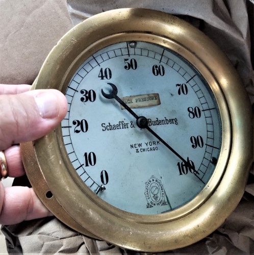
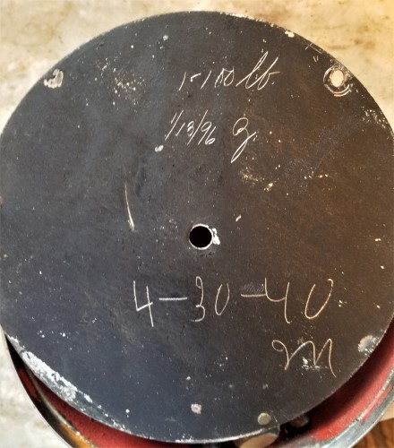
I obtained a 5" all brass (heavy) 0-100 PSI steam gauge. That can be read as 0-1000. Even with a huge 13x13 prop, this engine/boat combo pins the gauge which has a hard limit set in software at 700 rpm.
The book YT-1 redline is 800, but if I recall, I've read it can go to 1000 not that I would ever want to. I like 450-500 rpm the best, most relaxing speed although that's pretty slow across the water.
But will be nice to have the 1000 rpm gauge "headroom" and a brass gauge housing with a screw on front cover that with grease and sealed glass, wont leak any water at all.
This gauge has faded dark stains on the dial face that didnt want to clean up, so I will look to have a brass (no rust) plate cut to 5" diameter, and a white label made with similar markings but maybe with the extra digit, and a "Palmer Bros. Engine Co., Cos Cob Connecticut" brand mark on it. Which may confuse the hell out of some collector someday long after I'm gone... 
 |
    
chris_spring
Senior Member
Username: chris_spring
Post Number: 137
Registered: 02-2019
| | Posted on Monday, August 16, 2021 - 09:28 pm: | 


|
It'll look cool!
cheers! |
    
narrabay2
Senior Member
Username: narrabay2
Post Number: 199
Registered: 10-2019
| | Posted on Monday, August 16, 2021 - 09:40 pm: | 


|
Thanks Chris. I was told that even 800 rpm is iffy per Palmer due to risk of rod failure, and certainly not 1000 (I must have misread something) but it will be nice to have a scale that shows an over-rev like on startup for example... |
    
chris_spring
Senior Member
Username: chris_spring
Post Number: 138
Registered: 02-2019
| | Posted on Tuesday, August 17, 2021 - 11:03 am: | 


|
The Adams of course is quite different than the Palmer. I could hit 1000 rpm with it when it was under propped but it certainly seemed to be way too fast.
When I installed the latest prop, I checked it using a hand held digital tachometer. With that and a GPS I found that a hull speed of give or take 6 mph was best. That required about 750 rpm.
I try to never exceed 800. By now I can set it by ear. The tach isn't really required. Running it faster doesn't really produce a noticeable increase in speed, and it cuts into fuel economy.
Cheers! |


