| Author |
Message |
    
molliekv
New member
Username: molliekv
Post Number: 1
Registered: 01-2010
| | Posted on Friday, January 08, 2010 - 12:56 am: | 


|
Anyone aware of Wilson Engine Montreal? I have a 2 cylinder - appears to be a Waterman copper jacketed clone. Broken crankshaft. Appreciate if anyone has ever made their own or know of capable shop to reproduce the orginal. Very basic 2 cycle design. |
    
Don C
Visitor
| | Posted on Friday, January 08, 2010 - 07:54 am: | 


|
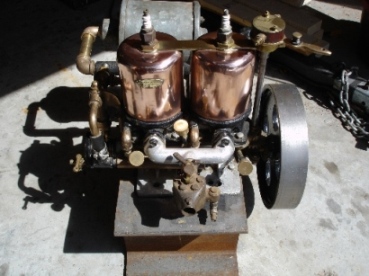
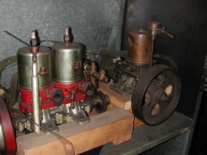
I also have a Wilson Twin. The Wilson Machinery Company is still operating. I have spoken to Peter Wilson who is 4th generation with the company.
At the time he had never seen one of these motors. After our discussion he found a single and a twin in an old storage shed.
 |
    
solarrog
Senior Member
Username: solarrog
Post Number: 404
Registered: 03-2002

| | Posted on Friday, January 08, 2010 - 12:00 pm: | 


|
Sure looks like my Waterman
Rog |
    
miro
Senior Member
Username: miro
Post Number: 418
Registered: 11-2001

| | Posted on Friday, January 08, 2010 - 01:30 pm: | 


|
If you look at
www.disappearingpropellerboat.com
705-765-5037
you'll see the contact info for the god-father of copper jacket engine repairs.
I think he's recently done several 2 cylinder engines and might just have a parts engine from which he could get a crankshaft.
Here's the link to pictures of his twin
http://www.disappearingpropellerboat.com/evelyn.html
And I know that he has the experience to get the job done. But you might have to be a bit patient.
In a pinch, I think that he's got contacts in a high-tech welding shop that might be able to weld the crank depending on where and how it is broken.
Any chance of getting some pictures - they really help. How complete is the engine - eg timer, water pump intake and exhaust manifolds, flywheel etc.
Fear not, though, you'll get 'er done.
miro |
    
raa
Member
Username: raa
Post Number: 9
Registered: 02-2007

| | Posted on Friday, January 08, 2010 - 04:47 pm: | 


|
Hi folks
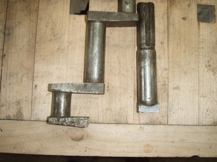
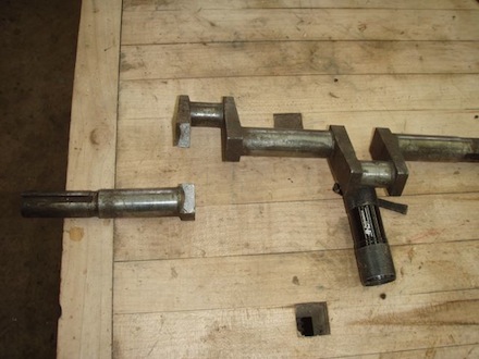
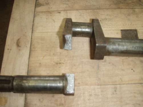
Funny you should ask about broken crankshafts! The pictures tell it all. What I would call a classic fracture propagation because there is no radius at all the changes in diameter or direction. This shaft was removed from Bob Visser's Wilson twin about two weeks ago in one piece! The first thing I noticed was the lack of any radius on any part of the shaft. Bob was removing the flywheel and the shaft literally fell in two pieces. I think the moral of the story is if you have any questions about a shaft get it magnafluxed. Not sure what we will do next. One thought I had was to get a rough crank blank flame cut out of 1020 hrs with disposable hubs also cut on both ends. This would allow cutting the throws and main bearing surfaces using 3 centers in the disposable hubs.
Dick
 |
    
rbprice
Senior Member
Username: rbprice
Post Number: 288
Registered: 11-2001

| | Posted on Saturday, January 09, 2010 - 08:11 am: | 


|
Dick - you would be better off using 1050/60 material. It has a higher yield strength and you could, after roughing it out, heat treat it up to about 25 Rc and then finish turning and grinding. And you are absolutely correct about the fillets in the corners and they should be polished to 63 or better finish. |
    
jb_castagnos
Senior Member
Username: jb_castagnos
Post Number: 497
Registered: 07-2002

| | Posted on Saturday, January 09, 2010 - 08:29 am: | 


|
That looks like the output side of the crank, if so it's a strange place for a break. You would think it would break between the crank pin and the flywheel where you have the most torsional stress. The broken twins I've seeen have all been between the cylinders. |
    
raa
Member
Username: raa
Post Number: 12
Registered: 02-2007

| | Posted on Saturday, March 06, 2010 - 12:32 pm: | 


|
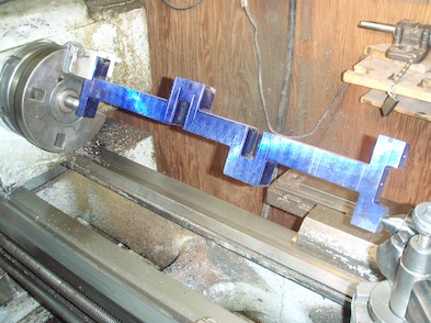
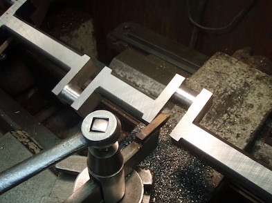
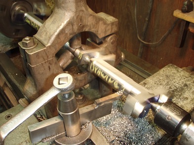
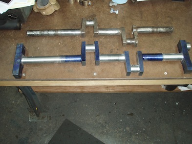
This is the replacement crank I made for the broken Wilson Engineering crank. Bob Price recommended using a higher carbon steel so I got a crank blank plasma cut from 1.25" 1045 plate which was annealed and blanchard ground to 1.125". the cost was $80. I then had a machine shop put the 3 centers in both ends and then the fun started. The machine shop charged $96. It took about 21 hours to get it ready for grinding. I was running the lathe slow so I could see and avoid any wrecks with the carriage etc which played hell with carbide tools which should be run at much faster speeds. High speed tools would not stand the interupt cuts. I had to make a few special tools to reach in the throws etc.
 |
    
john_archibald
Senior Member
Username: john_archibald
Post Number: 135
Registered: 08-2006

| | Posted on Saturday, March 06, 2010 - 01:00 pm: | 


|
Outstanding!
Archibald
Northfield, Minnesota
. |
    
miro
Senior Member
Username: miro
Post Number: 434
Registered: 11-2001

| | Posted on Saturday, March 06, 2010 - 08:09 pm: | 


|
atta boy
miro |
    
solarrog
Senior Member
Username: solarrog
Post Number: 417
Registered: 03-2002

| | Posted on Saturday, March 06, 2010 - 08:28 pm: | 


|
excellent work, far above my abilities |
    
jb_castagnos
Senior Member
Username: jb_castagnos
Post Number: 514
Registered: 07-2002

| | Posted on Sunday, March 07, 2010 - 07:51 pm: | 


|
Nice work, is that a bolt and nut used as a spreader between the throws? |
    
raa
Member
Username: raa
Post Number: 13
Registered: 02-2007

| | Posted on Sunday, March 07, 2010 - 08:50 pm: | 


|
Yes I was talking with Bob Skinner and he said it might help. I think it actually put a little bow in the shaft since you have no idea how tight to make it. If it is too loose it simply falls out too. I think a better way would be to take a couple of pieces of 1/2x 2 crs and clamp across the throws with a pair of 1/2-13 bolts which could be set up real tight with out putting any stress toward bending the shaft since I had both sides blanchard ground.You would remove one when machining a rod journal and then replace it. |
    
axtion_jim
Advanced Member
Username: axtion_jim
Post Number: 35
Registered: 01-2006
| | Posted on Monday, March 08, 2010 - 12:15 am: | 


|
Nice machining work , but do I notice that a radius is missing on the throws. Its not clear in the photos. |
    
raa
Member
Username: raa
Post Number: 14
Registered: 02-2007

| | Posted on Monday, March 08, 2010 - 08:13 am: | 


|
Jim
I made sure that there is a radius of about .060 plus a lot of stock. As you increase the radius you also increase the tool pressure and chatter. I felt that the best way to get a good radius is to grind it in so I left a lot of stock.
Dick |
    
raa
Member
Username: raa
Post Number: 15
Registered: 02-2007

| | Posted on Thursday, March 11, 2010 - 03:44 pm: | 


|
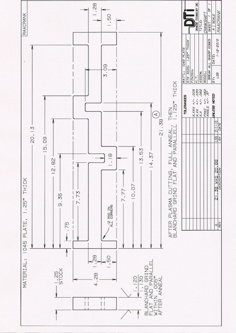
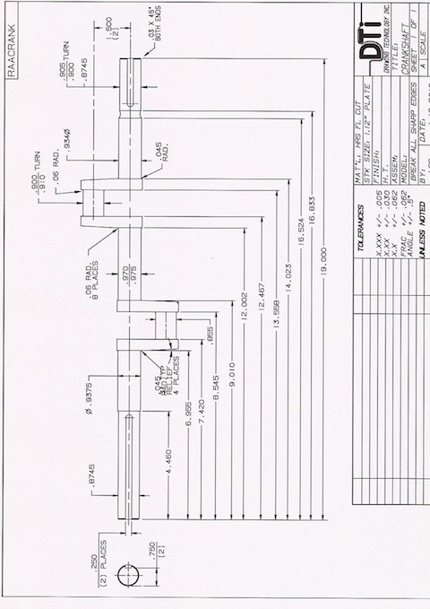
These are the drawings I used to make the crankshaft
 |
    
axtion_jim
Advanced Member
Username: axtion_jim
Post Number: 36
Registered: 01-2006
| | Posted on Thursday, March 11, 2010 - 07:03 pm: | 


|
Dick
Thank you for the drawings,I have made a copy and have them filed away should I have the need. I`m wondering if the twin engine that I have perhaps it maybe a Willson being in Canada and all.
Jim |
    
john_archibald
Senior Member
Username: john_archibald
Post Number: 136
Registered: 08-2006

| | Posted on Thursday, March 11, 2010 - 07:13 pm: | 


|
I thought this was a neat way of doing things. By leaving some steel at each end you can drill in the various centers that are needed to machine the thing. Very clever I thought. Not sure if this is a well known crankshaft making scheme, but very good nevertheless.
Archibald
Northfield, Minnesota |


