| Author |
Message |
    
Don Crowell
Visitor
| | Posted on Sunday, January 02, 2005 - 07:10 pm: | 


|
Have located an old single cylinder Palmer Bros. gas engine. It was used to hoist ore at a small mine sometime in the 1920s. No serial No. just "PALMER BROS COS COB CONN" cast into plate on crankcase.I am interested in learning more about this engine and if it is worth retrieving (which would be a big job since there is no road to the site). I would appreciate hearing from anyone on how I could find more information. Thanks |
    
andrew
Moderator
Username: andrew
Post Number: 1001
Registered: 11-2001

| | Posted on Sunday, January 02, 2005 - 07:58 pm: | 


|
Don,
You will probably need to supply some more information.
Can you describe the engine, or do you have pictures of it? What condition is it in? Is the cylinder badly rusted and cracked?
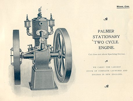
Palmer made stationary versions of many of the early models. They were put on a cast iron base, two flywheels instead of one (also larger diamenter flywheel than the marine), no water pump (tank cooled), and flywheel governed. Below is a picture of a very early model.
 |
    
richardday
Senior Member
Username: richardday
Post Number: 342
Registered: 11-2003

| | Posted on Sunday, January 02, 2005 - 07:55 pm: | 


|
Can you describe in a little more detail. Is there a raised letter,s cast into the front of the cylinder lower section? EG. NR, NL, ZR, L, Q, etc. Is it a two stroke or four stroke? T head with a dome shape and round covers over the valves? Detachable head? Approximate size. Not being near salt water one would expect the cylinder might be good without the water jacket cracked. from salt. Depending on the model the most valuable part is the cylinder and piston if they are worth recovering. Give me more to work with and I will try to give you a better feel for the find. |
    
Don Crowell
Visitor
| | Posted on Tuesday, January 04, 2005 - 12:35 pm: | 


|
Andrew,Richard,Thanks for responding.
Engine looks something like picture posted but has single flywheel and is four stroke. Housing between cylinder and crankcase contains two camshafts, one driving intake valve and water circulating pump and other driving exhaust valve. Lower shafts and springs of valves are visible.No raised letters on cylinder visible. Engine locked but no damage evident. I do have pictures but unsure how to post. |
    
andrew
Moderator
Username: andrew
Post Number: 1004
Registered: 11-2001

| | Posted on Tuesday, January 04, 2005 - 01:47 pm: | 


|
Don,
If your pictures are "digital" you can read the instructions in the help section (see above) and post them here. The files size of each photo must be under 40Kb so they may have to be reduced in a photo editing program. Or could also email them to me and I will post them.
If they are not "digital" photos you will have to scan them on a scanner.
Regards,
Andrew |
    
Don Crowell
Visitor
| | Posted on Wednesday, January 05, 2005 - 06:32 pm: | 


|
Andrew, will attempt to post picture with this. On looking through pictures find that there are raised letters cast on cylinder: (R W) and brass ID plate RW 149832) RW 149832)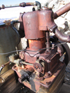 |
    
andrew
Moderator
Username: andrew
Post Number: 1008
Registered: 11-2001

| | Posted on Wednesday, January 05, 2005 - 08:17 pm: | 


|
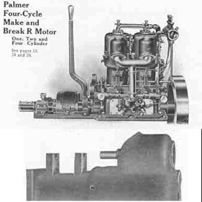
We should be able to post a larger picture. Email the original to me if you want and I will post it larger. actually I think I can do it from the picture you posted... it appears to be small in pixels, but still a large file size... I will try to modify it. The image below isn't very good but it shows a 2 cylinder "R"
 |
    
andrew
Moderator
Username: andrew
Post Number: 1009
Registered: 11-2001

| | Posted on Wednesday, January 05, 2005 - 08:30 pm: | 


|
Well... I've enlarged the photo somewhat but the quality is not good. Send me the orginal by email if you can Don.
Seems to be a "marine version" converted to stationary use rather than a "stationary verison" from the factory.
I think Dick Day is having computer trouble and may not be online, but he will be thrilled to see this.
I don't know how "inaccessible" it is, but IMO that is a engine worth saving!
See better pictures below... |
    
richardday
Senior Member
Username: richardday
Post Number: 343
Registered: 11-2003

| | Posted on Thursday, January 06, 2005 - 11:15 am: | 


|
It certainly looks like an RW-1 and seems to be complete on the stern section. The water pump appears to have built in check valves which suggests post 1919. The 149832 serial number is missing a diget. If the last two are correct then the engine was assembled from in house parts in 1932 as the Model RW-1 went out of production in about 1925. The 149832 portion could be correct for and RW-1 because that would put the engine in production around 1919-20 but that then suggests that the last digit would need to be 0. Any chance we can get another reading of the serial number. There should be seven digits.
As this engine probably never got near salt water it should be a very nice unit to retrieve.
I wonder if the brass cap over the flywheel hub is still present and if a puller nut or gib key hold the flywheel on to the shaft? I would expect the puller nut if it turns out to be a post 1922/3 engine and gib key prior to that time.
Andrew, I am partially back on the internet meanwhile waiting for a new pooter. |
    
Don Crowell
Visitor
| | Posted on Thursday, January 06, 2005 - 01:05 pm: | 


|
Andrew, If you can give me your E-mail address I will attempt another picture(s). Cannot use your link because my computer still thinks I am using AOL but have switched to MSN
Richard, There is possibly a "0" at end of serial No. Definitely is a key on flywheel as I sprayed it with WD 40 on last visit preparing for possible disassembly. |
    
andrew
Moderator
Username: andrew
Post Number: 1010
Registered: 11-2001

| | Posted on Thursday, January 06, 2005 - 04:53 pm: | 


|
Don,
You can send them by email to me at [email protected] |
    
richardday
Senior Member
Username: richardday
Post Number: 345
Registered: 11-2003

| | Posted on Thursday, January 06, 2005 - 08:25 pm: | 


|
Don, Don't try to pull the flywheel. The nice thing about the NL, NR, RW, ZR etc family is the split crankcase allows you to pull the cylinder off by disconnecting the Big End of the con rod. Take out all the cap screws that hold the top half of the crankcase to the bottom half. Take out the four cap screws that hold the cylinder to the top half of the crankcase. Therebye reducing the major parts to four items. Watch out some of the cap screws are 1/2" 12 THD not 1/2" 13 THD. Don't think you can tap a 12 to a 13 all you will do is ruin the threads. Flywheel with connected crankshaft, crankcase bottom half with the oil pump and water pump easily removed leaving the bearing halfs of the crankshaft in place. Remove the oil and water pump straps at the ecentric by removing the screws holding the straps to the ecentric. Don't pull the cast iron ecentric until you get the unit home and have time to work on it. It is very easy to crack the ecentric trying to pull the gib key. You can get modern lip seals that will fit the shaft and be properly mounted in the brass cap. Pulling a rusted flywheel can be a real problem and don't use heat to expand it as you are creating a ticking time bomb with a spoked flywheel. Clean it up with the shaft still connected and you never have to worry about it coming loose at a show or worse a cracked flywheel hub. Keep in mind these Palmer engines all run counter clockwise facing the flywheel. Occasionlly some one may have retimed the camshafts to run clockwise but that is so rare I would assume your engine runs counter clockwise. If you run into trouble with parts let me know and I may be able to help. To remove the piston from the cylinder plug all the ports and fill with oil. Put a 1/2" pipe plug in the center of the head with an grease fitting in it and a few sqwirts of grease should break it loose once moved the rest just takes patience and care. Hope the Cuno timer is still there as they are not easy to find. You can get a ZR manual from Andrew that will tell you much of what you need to know. If you need more help come back to me and I will try to give you a few ideas. Easy on the hammers and torches. Old cast iron is like Ginger Snaps and not very forgiving. If it is a 0 then the engine was made in 1920 and the serial number fits the pattern for those years around the early 20s. Good luck on a great find. |
    
andrew
Moderator
Username: andrew
Post Number: 1014
Registered: 11-2001

| | Posted on Saturday, January 08, 2005 - 12:34 pm: | 


|
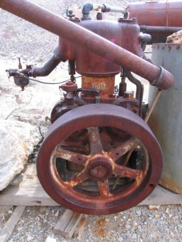
Don has sent me a couple of higher resloution photos... here they are:
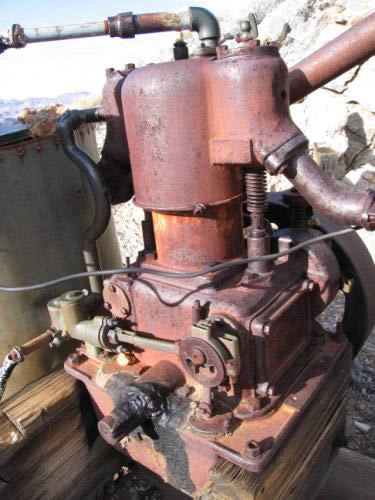 |
    
richardday
Senior Member
Username: richardday
Post Number: 347
Registered: 11-2003

| | Posted on Saturday, January 08, 2005 - 01:54 pm: | 


|
Interesting the way the Palmer intake manifold has been inverted to permit side draft operation. Looks like model T Ford carburetor. What does the wire around the lower part of the water jacket do? Hope it is not cracked and it is holding the water jacket together. Water pump check valve covers have the early small hex heads. These were changed at a later yet unknown date to large hex heads about 1" in dia. Oil line is iron pipe through the crankcase. It has no priming cup. Just a pipe plug. Don may want to replace it so he can prime the oil pump if it loses its prime. Spark plug belongs over the intake valve. Should be a 1/2" NPT in that valve cover along with the priming cup. The 1/2" NPT in the center of the cylinder was intended to be used to set the valves by measureing the position of the piston in the cylinder. I have found trying to use that position for the spark plug makes for difficult running. Moving it to the intake valve cover really can make a big difference when idling down. Wonder where the serial number tag is located? Amazing the Cuno timer has not been stolen long ago. This engine is early in the RW development program. This round cylinder would not fit on the standard NR multiple cylinder crankcase so Palmer flatened the fore and aft faces which turned out to be a disaster as the thickness of the outer water wall had to be reduced which in turn made them very vunerable to salt water rust and early failure. Starboard side lower half of the craankcase is milled for a magneto mounting. I cannot seem to find a breather valve anywhere on the engine. Curious. The oil fill is simply a sliding plate. When did they go to a 3/4" NPT winged cap? Questions, Questions?? An interesting find. |
    
Don Crowell
Visitor
| | Posted on Saturday, January 08, 2005 - 06:23 pm: | 


|
Andrew,Richard, I would like to get that manual if it would help with dissambly. Each piece of this engine will have to be carried out by hand over short but steep,treacherous trail so will have to break down into lightest possible pieces.
This, of course, is why engine is still here completely out in the open for some 80 years! |
    
rholcomb
Member
Username: rholcomb
Post Number: 5
Registered: 10-2004
| | Posted on Saturday, January 08, 2005 - 08:24 pm: | 


|
A piece of advice dont put the piston back in a headless cylinder,it will drop to the bottom and the rings will expand and ruin all of the assy
learned the hard way......... |
    
andrew
Moderator
Username: andrew
Post Number: 1015
Registered: 11-2001

| | Posted on Saturday, January 08, 2005 - 08:38 pm: | 


|
Don,
Here is the link to the shopping cart for that Palmer ZR manual , just click on it and then follow the instructions.
Palmer ZR manual |
    
richardday
Senior Member
Username: richardday
Post Number: 348
Registered: 11-2003

| | Posted on Sunday, January 09, 2005 - 09:50 am: | 


|
RH, is right. I made up a 1/2" NPT plug with a 8" length of all thread and a wing nuts to lock it at the distance I want to keep the piston from traveling up to the very top of the cylinder. I used to just put a block of 2x4 but wanted to be able to be sure that I had plenty of clearance below the lip at the top of the cylinder. What ever you do don't leave it in place once the con rod is connected to the crankshaft or you could run the all-thread through the top of the piston. I have not managed to do that dumb thing but I have done more than my share of dumb things which shall be nameless.
Once you have the major parts separated a small two wheel baggage truck will easily handle the individual items. The heaviest and most vunerable to damage item will be the crank with the flywheel attached. The alternative of trying to remove the flywheel is far more likely to damage than keeping them together. One of the reasons most makers by about 1906-8 changed to split crankcases along the crankshaft line was they broke so many in the factory trying to service engines brought in for factory repair. I read that in one of the early Motor Boat articles. J.W. Lathrop never learned that lesson with his two strokes. |
    
Don Crowell
Visitor
| | Posted on Sunday, January 09, 2005 - 11:35 am: | 


|
Gentlemen, thanks for advice. I'm going out of town for week or so. I live in Tucson, AZ and engine is located in Nevada. Plan to travel to the site in late Feb for other work and will,hopefully, have a couple of days to work on disassembling engine. Will advise on progress and probably be asking for more advice. |
    
thomas
Senior Member
Username: thomas
Post Number: 243
Registered: 07-2002

| | Posted on Sunday, January 16, 2005 - 10:41 am: | 


|
That RW-1 is a great find. I have one and although I have to take the flywheel off to move it in and out of the van, it's a good runner and with all the water and oil pump action on the back it makes a great show engine. I read about these western mining hardware artifact finds but this is the best looking one so far. Good luck
on the project.
Tom |
    
richardday
Senior Member
Username: richardday
Post Number: 349
Registered: 11-2003

| | Posted on Monday, January 17, 2005 - 07:56 am: | 


|
Tom, does your RW-1 have a gib key or puller nut on the flywheel? |
    
thomas
Senior Member
Username: thomas
Post Number: 244
Registered: 07-2002

| | Posted on Monday, January 17, 2005 - 01:17 pm: | 


|
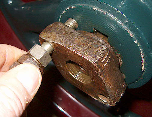
I'm posting a picture of my RW-1 and 3 shots of the flywheel nut area. Yes Richard, it has a left-hand nut with holes to allow 2 bolts to pull the wheel off the tapered crankshaft and key.
The flywheel is about all I can carry getting the whole thing in & out when going to shows.
Tom |
    
thomas
Senior Member
Username: thomas
Post Number: 245
Registered: 07-2002

| | Posted on Monday, January 17, 2005 - 01:18 pm: | 


|
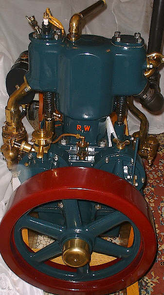 |
    
thomas
Senior Member
Username: thomas
Post Number: 246
Registered: 07-2002

| | Posted on Monday, January 17, 2005 - 01:20 pm: | 


|
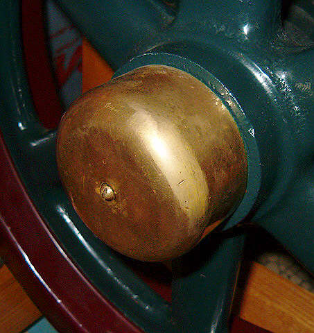 |
    
thomas
Senior Member
Username: thomas
Post Number: 247
Registered: 07-2002

| | Posted on Monday, January 17, 2005 - 01:21 pm: | 


|
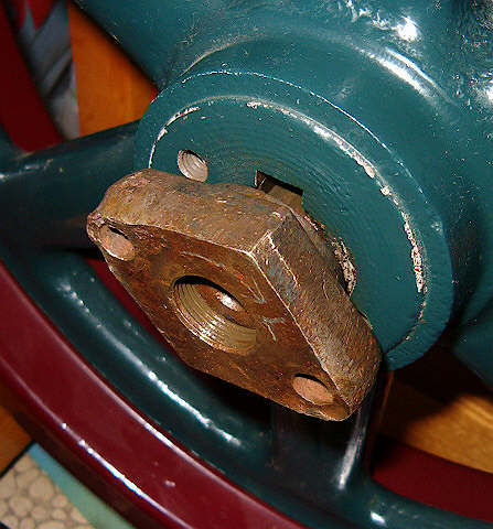 |
    
thomas
Senior Member
Username: thomas
Post Number: 248
Registered: 07-2002

| | Posted on Monday, January 17, 2005 - 01:22 pm: | 


|
 |
    
richardday
Senior Member
Username: richardday
Post Number: 350
Registered: 11-2003

| | Posted on Monday, January 17, 2005 - 02:58 pm: | 


|
Great, that suggests your RW-1 is post 1922. Yours has the flat sided cylinders that came out at some date after 1918. Have not been able to establish a firm date when they went to the flat sided cylinder on the RW model. Your puller cap screws look like they are 1/2" 12thd. My NR-3 has a puller nut and tapered crankshaft but the the threads for the puller function are 3/8" 16 thd. I broke one off just below the cap screw head. I had not bottomed it and had cleaned out the threads and coated them with anti seize before trying to pull the flywheel I took a dental pick and managed to back the broken cap screw out of the puller nut enough to grab it with pliers and back it all the way out. I always put two washers under the head to minize friction but in this case the cap screw broke off just inside the puller nut. I bought a couple of class 5 cap screws and use them now to apply the pressure but actually a peice of bronze shaft and a sharp rap on the end of the crankshaft once you have applied a good amount of balanced pressure from the cap screws is what I find really breaks the flywheel loose from the crankshaft rather than the puller nut cap screws. Too easy to strip the threads in the flywheel doing it that way. One thing I do that I wish someone would tell me if my practice of applying never sieze to the taper shaft and keyway is a good or bad practice. Having done it for many years with no problems I wonder what others think of the practice.
Incidentally I have flywheels for the tapered shaft crankshaft on the RW, NR, ZR series that have threads for the puller nuts 3/8" 16Thd, 1/2" 12Thd and 1/2"13Thd. So one needs to be carefull to figure out what thread you are dealing with before starting to pull the flywheel. It is easy to separate 1/2"12 Thd from 1/2"13 simply by trying to screw a known 1/2" 13 Thd cap screw into the threaded hole and if it is 12Thd it will go about 1-2 turns before locking up. Don't force it and don't tap it our to 13THD all that will do is destroy the 12 Thd. and it will be no good for 13 Thd. |
    
Don Crowell
Visitor
| | Posted on Thursday, February 24, 2005 - 07:29 pm: | 


|
Richard,Andrew, happy to report that my brother, nephew and I(mostly the 40 something nephew) retrieved the old engine last week. Took it apart per your advice and packed the three lighter sections out on a pack frame. Made a stretcher of two 2 X 4s through the flywheel to carry the flywheel/crankshaft. Engine is in remarkably good shape considering it spent 80 some years out in the weather. All metal bearing surfaces are good with only light rust on the camshaft gearing. Exhaust camshaft and piston remain locked. What in the world is purpose of lever that appears to slide exhaust camshaft gear on its shaft? Am soaking these parts with WD 40 to loosen. Is there a better rust solvent? Will try moving piston with oil and grease gun after a little more WD 40.The wire around the water jacket is fairly sophisticated clamp with no obvious purpose, so water jacket may be cracked but nothing visible.
Don |
    
andrew
Moderator
Username: andrew
Post Number: 1081
Registered: 11-2001

| | Posted on Saturday, March 12, 2005 - 10:47 am: | 


|
Some more info from Don:
quote:...
The engine appears to be in remarkably good shape. The only parts still frozen are the exhaust camshaft assembly, piston, and intake valve. Want to use your recommended oil/grease gun method to free up the piston but have to get that intake valve closed first. I re-read your last E-mail Richard and now understand that the lever on the exhaust camshaft is indeed a compression release. That whole assembly may be the hardest item to free up as it is pretty badly rusted. A couple of other comments/questions:
1- There is no location for the spark plug over the intake valve; just the 1/2 NPT hole directly over the piston.
2- The wire around the water jacket now appears to be a "jury rigged" arrangement to close the small drain hole on the bottom of the water jacket. There was no plug in this hole.
3- Inscribed on the inside of the intake camshaft cover plate/bearing support is the following: N R & N L 67 A Mean anything?
Regards, Don Crowell
Thanks Don. Keep us posted on your progess, and post some more pictures when you get a chance! |
    
richardday
Senior Member
Username: richardday
Post Number: 373
Registered: 11-2003

| | Posted on Saturday, March 12, 2005 - 01:38 pm: | 


|
Don, Looks like you have a winner. What is the serial number? The number 149832? is lacking a digit for pre 1922/3 when the shift from gib key to left hand puller nut and tapered crankshaft took place. Could be a 0,1 or 2 for 1920, 21 or 22
The RW came on stream in 1919 and the flat sided cylinders like Tom's are probably post 1923. The RW went out of production in about 1925 with the advent of the ZR. The RW cylinder was an attempt to get a bigger bore and therefore more horspower from the basic NR. You will find it bored either 5-3/8" or 5-1/2". I suspect the 5-1/2"BORE came first and then when they went to the flat sided cylinders they dropped it to 5-3/8" in attempt to solve the rust out problem the thinner water jacket caused in salt water. I would like to know what the bore is in both Don and Tom's engines. So few RWs have survived every little bit helps reconstructing history. I try to be very careful to separate speculation from fact and its not alway easy to come up with facts. Tom has a very nice restoration and I bet it idles down to about 120 quite easily.
Don the NR & NL 67 A are mold numbers and I put a warning in the ZR manual reprint that those really don't mean much as you will find the identical numbers on the intake drive gear housing for the post 1936 housings when the shift to 5/8" wide from 1/2" wide magneto drive gears took place. Both housings look almost the same and either will work with the 1/2" gears as the post 1936 housings have about 1" gear clearance vice the 5/8" clearance for the 1/2" gears. I note Don's oil fill port on top of the exhaust camshaft support is the swinging plate type vice the 3/4" wing nut pipe plug on Tom's. Tom is there a crankcase breather valve behind the intake valve guide on your RW-1 or is there one on the aft upper face of the crankcase? Some people not knowing the purpose of the breather valve plug the hole with a pipe plug. |
    
andrew
Moderator
Username: andrew
Post Number: 1100
Registered: 11-2001

| | Posted on Wednesday, March 16, 2005 - 07:03 pm: | 


|
Wow... when Don said the engine was in a remote location he wasn't kidding!
Thanks for sending these in Don!
quote:Richard,
the full serial number stamped on the I D plate is: RW1-1498320. The bore is 5.5 inches.
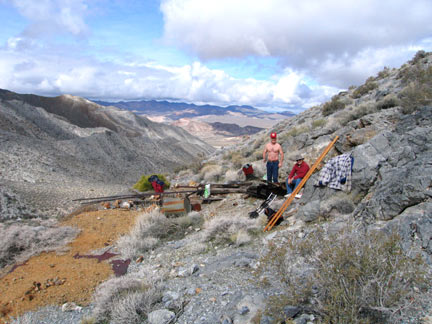
The first picture is the location of the engine, thought you might like to see just how far from salt water a Palmer marine engine can stray!
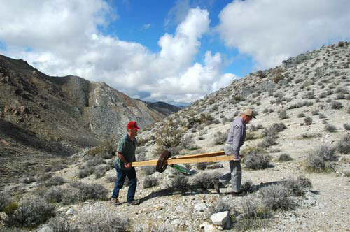
2nd photo is my nephew and me with flywheel_crankshaft and
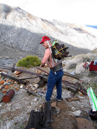
3rd photo is my nephew with upper crankcase on a pack frame.
 |


