| Author |
Message |
    
narrabay2
New member
Username: narrabay2
Post Number: 1
Registered: 10-2019
| | Posted on Sunday, October 27, 2019 - 10:40 pm: | 


|
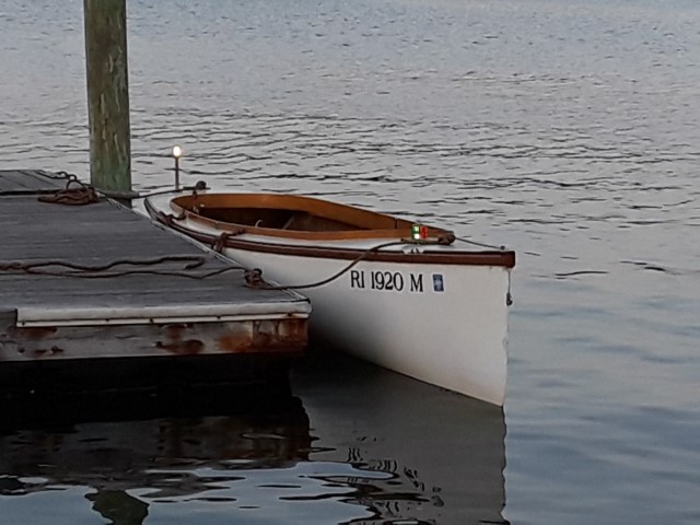
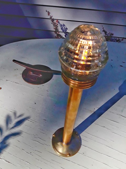
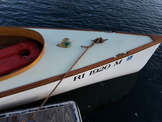
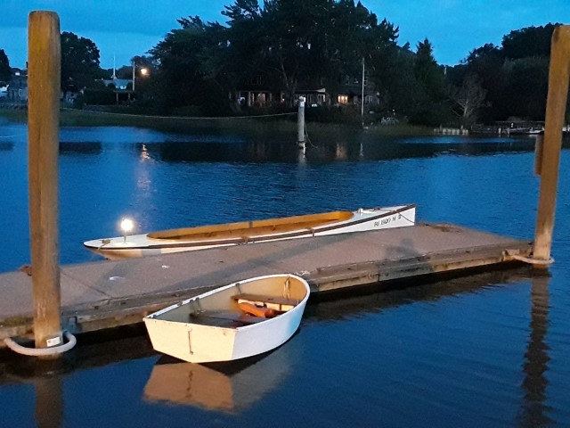
Here are the Perko brass running lights added to my (Formerly Ernie's) fantail. Took it for a night cruise as well. Future update is the Palmer going into it to gain shifting ability.
 |
    
narrabay2
New member
Username: narrabay2
Post Number: 2
Registered: 10-2019
| | Posted on Monday, October 28, 2019 - 01:24 am: | 


|
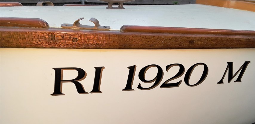
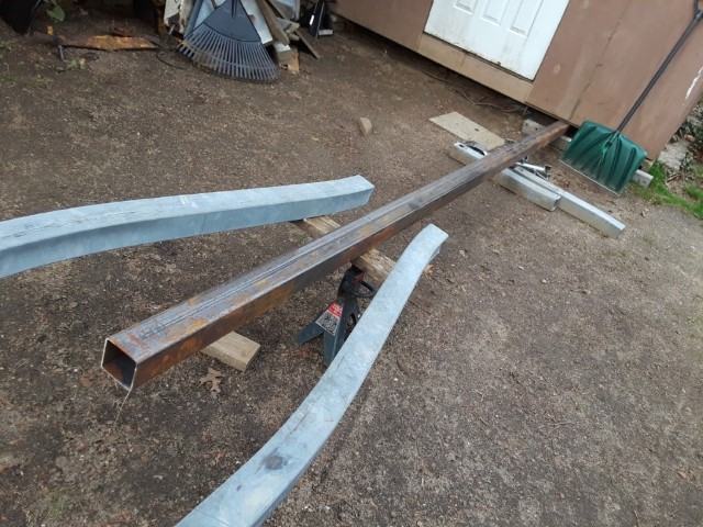
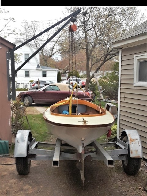
A few more pics, trailer build, lettering
 |
    
narrabay2
New member
Username: narrabay2
Post Number: 3
Registered: 10-2019
| | Posted on Monday, October 28, 2019 - 01:38 am: | 


|
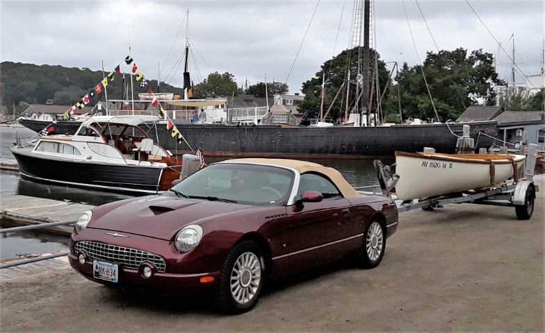
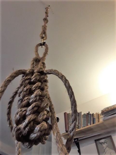
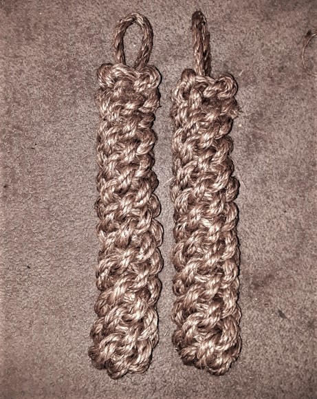
Making The Rope Fenders (put a hook into living room ceiling) and Mystic 2019:
 |
    
ned_l
Senior Member
Username: ned_l
Post Number: 197
Registered: 08-2012
| | Posted on Friday, November 01, 2019 - 12:20 pm: | 


|
very nice! I like the fenders too.
(you got my boat in the background there. lol) |
    
narrabay2
Member
Username: narrabay2
Post Number: 4
Registered: 10-2019
| | Posted on Friday, November 01, 2019 - 05:37 pm: | 


|
thanks ned, I chose that pic for that reason! nice meeting you, hope to see u next year too. |
    
ned_l
Senior Member
Username: ned_l
Post Number: 201
Registered: 08-2012
| | Posted on Friday, November 08, 2019 - 03:53 pm: | 


|
Thank you, Hope to see you too, .... it's a great show! |
    
narrabay2
Advanced Member
Username: narrabay2
Post Number: 31
Registered: 10-2019
| | Posted on Saturday, April 18, 2020 - 01:55 pm: | 


|
Well the YT is going into the Fantail and it was time to try to learn how to make a propeller shaft. Used a length of 1018 for practice. The threads were difficult and it took many different kinds of tooling and speeds etc but it finally started to more or less cut rather than rip the material. I got it close and then cheated the last few thousandths with a 3/4-10 die.
Ernie told me that the taper could be turned on my SB H10 lathe with just the compound (no need for a taper attachment) and that is correct I was happy to find out.
The 1" 304 stainless for the actual prop shaft is plenty long so there will be many chances to get it right, as I understand that material has its own machining issues to get used to. A couple vids of making the practice prop shaft out of 1018 steel.
Making the threads:
https://youtu.be/ZCmmH5l2gII
Turning the taper:
https://youtu.be/WO2QHe1b8U0 |
    
miro
Senior Member
Username: miro
Post Number: 1074
Registered: 11-2001

| | Posted on Saturday, April 18, 2020 - 03:38 pm: | 


|
It's looking good - quite a hefty cut on that 3/4-10 thread.
Looking forward to seeing the boat in the water and cruising.
Miro |
    
narrabay2
Advanced Member
Username: narrabay2
Post Number: 32
Registered: 10-2019
| | Posted on Saturday, April 18, 2020 - 06:18 pm: | 


|
Thanks Miro, stay well! I hope we defeat this terrible virus soon.
Here's a sample I threw together. Ernie had the boat pretty ship shape so what you see is his doing, I'm just the operator. I only added the running lights. Hopefully swapping the YT into it goes without a hitch and the much lighter Gray will go well with the Dispro.
https://youtu.be/OgPihBw-FcI |
    
ned_l
Senior Member
Username: ned_l
Post Number: 215
Registered: 08-2012
| | Posted on Monday, April 20, 2020 - 09:33 pm: | 


|
Very nice!
Where were you? I almost want to say Wickford? |
    
narrabay2
Advanced Member
Username: narrabay2
Post Number: 33
Registered: 10-2019
| | Posted on Monday, April 20, 2020 - 11:34 pm: | 


|
Exactly! Wickford RI - Grew up there and made inboard boats using a horizontal shaft cast iron Briggs model 5S. First boat was an old washed up wooden dock. I used conduit for a prop shaft and a loaner LH bronze outboard prop. The 16p nail I used to join the conduit to the engine (after drilling it through) broke, and away went the shaft and prop. But hey, I was 12! After that, I used a plywood dinghy and made a shaft log with stack of plywood drilled with a paddle bit. Needless to say it leaked a lot. So I added a washing machine pump sourced from the town dump scrap pile. As soon as the boat took on 3 or 4 inches of water, it would catch prime and drain it back down. Worked great! Until the engine stopped. Ended up swimming dragging the swamped rig to shore many times. Then I picked up a fiberglass swan dinghy, embedded a 1928 Johnson lower unit in the skeg with fiberglass and sealed the exhaust passage. The engine went on the back seat, with a belt driving a F-N-R riding mower gearbox again sourced at the dump. Under the seat was another set of pulleys, which I could change to play with ratios. That was the ticket and a very reliable boat, finally.
There was one other edition, a plank dinghy which was the cut off front of a workskiff, that was the first to have the lower unit system, but i used a 3.5hp vertical shaft. It even had a plywood deck and a Boston Whaler Outrage windshield that was discarded, and an old cable steering wheel too. That model was actually quite "fast" with "all that power" haha! It tended to vibrate the seams though and leaks were a constant issue. Thats why I went to fiberglass.
I think I sank in more boats in that harbor than anyone else, and my friends and I had fun every minute. |
    
narrabay2
Advanced Member
Username: narrabay2
Post Number: 34
Registered: 10-2019
| | Posted on Tuesday, April 21, 2020 - 12:28 am: | 


|
Here's a short video making the stainless prop shaft today. Taper turned out a little shallow. About .007" undersize at the prop big end. It would probably snug up ok, but not sure how good that is for the bronze prop hub (could it split perhaps?) , and in any case will be harder to remove. So may cut it off and do it again. I matched an old prop shaft (the one from the Dispro project actually) which is slightly bent. I split the difference using an indicator and turning it so the runout was halfway, then chased that with the compound until it matched. BUT, apparently something was amiss. Maybe a better way will be to do it mathematically. The SAE J755 standard 1:16 taper results in a .828" diameter small end and a 1" big end with a taper length of 2.75". So with a correct compound angle, the gap should start at half of .172" which is .086" at the big end, and when moving the carriage back exactly 2.75", close up that gap. (says the guy who will probably have a basket full of cut off taper attempts by Friday!)
https://youtu.be/gM4mnJetK-g  |
    
miro
Senior Member
Username: miro
Post Number: 1076
Registered: 11-2001

| | Posted on Tuesday, April 21, 2020 - 11:36 am: | 


|
Using the info you showed, the angle is 1.79 degrees
or about 1 3/4 degrees. You should be able to get the compound set to that angle.
The graduation marks on the compound angle setting are about 1/4 degree. I frequently use a magnifying glass to set it .
A test cut on a piece of ordinary mild steel will tell you - I mark the taper with a Sharpie and then test fit the prop to see what I need to adjust.
I made an attachment showing the geometry and the math, but the upload function seems to be stalled.
Miro |
    
miro
Senior Member
Username: miro
Post Number: 1077
Registered: 11-2001

| | Posted on Tuesday, April 21, 2020 - 11:44 am: | 


|
Got the upload working (the usual problem - operator error)
Here's the sketch with the geometry
Miro
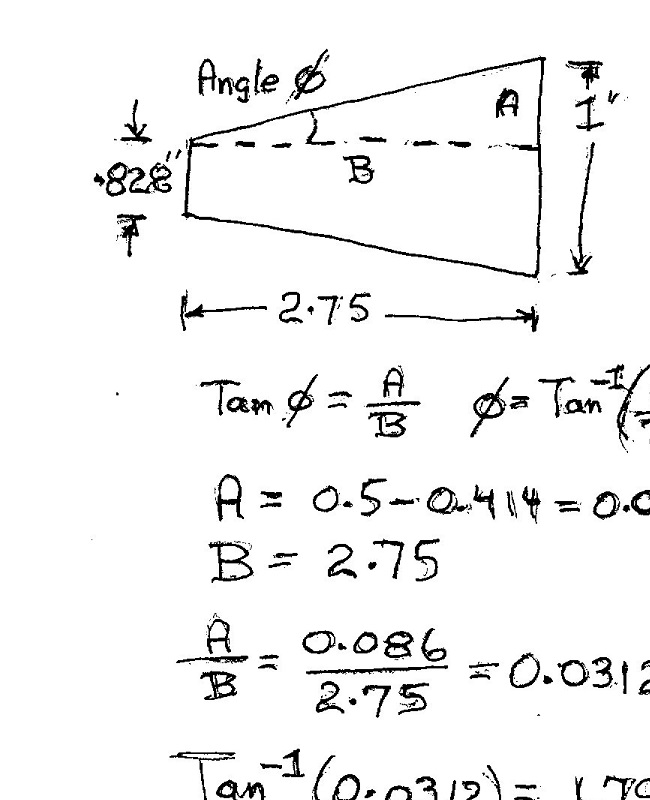
(Dang ! - more operator error - cut off part of te scan - but the essential info is there)
I use a scientific calculator to get the inverse Tangent (Tan) function. I don't use it often but when needed it's great to have it. |
    
narrabay2
Advanced Member
Username: narrabay2
Post Number: 35
Registered: 10-2019
| | Posted on Tuesday, April 21, 2020 - 12:57 pm: | 


|
Hi Miro, thanks. If you scroll up you'll see that I did make a practice run on some 1018 steel. When setting the compound, it is turned past the graduation marks which are one degree apart anyway which is too course. (you'll see this in the video above). That's why I used the dial indicator also shown in the video above to match an existing prop shaft. I believe the issue is the bent shaft I used as an example. Rotated the prop shaft until halfway between high parts at the end with the dial indicator thinking I'd get the correct taper facing the tool that way, and then zeroed the dial indicator to that across the taper.
Next time I plan to put that 1018 back in with a live center, take a light cut to true it to the bedways, then set the compound per your drawing and as described above for the right amount over the 2.75" taper length. This is very fun.
In case anyone is still reading at this point, I found a video on lapping a prop to a shaft by a machinist on Cape Cod. (wouldnt be the right way to fix my 7 thousandths issue though!)
The person is clearly very good at what he does. I just wonder how much that takes from the prop hub bore rather than the shaft especially on bronze (his example is a harder nibral prop) But it's nice to watch someone doing something apparently very right, and a nice video too.
If you love boats, propellers, etc, Keith F's prop bore matching video below is a pretty nice video to watch while we all on home confinement (there is 2 parts):
https://youtu.be/2ozh4JjoWm4 |
    
narrabay2
Advanced Member
Username: narrabay2
Post Number: 36
Registered: 10-2019
| | Posted on Friday, April 24, 2020 - 05:37 pm: | 


|
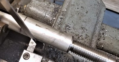
Ok I did a little simplified "Miro-izing" (math, only at my level). The compound only moves a little more than 2", so how far away from the prop shaft before cutting the taper does the compound need to be at 2" when it has the correct taper angle... and its 1-.828= .172, divide that in half for .086" at 2.75" (the end of taper), so it's .086"x2/2.75 which is .0625" I stacked two feeler gauges (.030 and .032) and set the taper so it starts at the shaft and has a .62+ gap after moving it 2" forward. Worked perfect! Nice even fit, no rocking. Video: https://youtu.be/79PmkeLpBmw
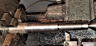
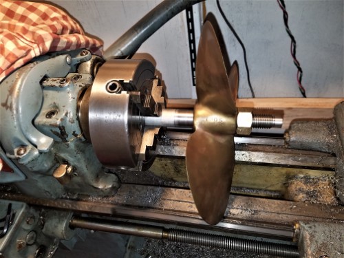 |
    
narrabay2
Advanced Member
Username: narrabay2
Post Number: 40
Registered: 10-2019
| | Posted on Friday, May 01, 2020 - 07:51 pm: | 


|
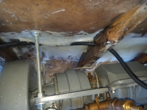
Out came the Gray engine. That will go well with the repro-Dispro project. Dropped the YT in and it happened to land in what looked to be a very good place regarding the existing ribs. I can make two engine bed stringers and tie them to no less than 4 ribs/crossmembers with heavy duty fiberglass work. The prop shaft works out to about 7ft. The fiberglass stern tube brings that forward as much as practical, prob 3ft to an inside stuffing box. (I have 5ft of the tubing). This diversion from the cyl head is actually good for sharpening my machining skills before getting after the valve guides on that project, which have to be precise. It will be nice to have a gearbox and optionally an electric starter on the fantail once the YT is in place.
A few pics:
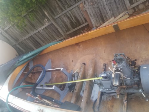
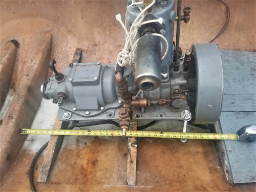
 |
    
narrabay2
Advanced Member
Username: narrabay2
Post Number: 41
Registered: 10-2019
| | Posted on Saturday, May 02, 2020 - 06:28 pm: | 


|
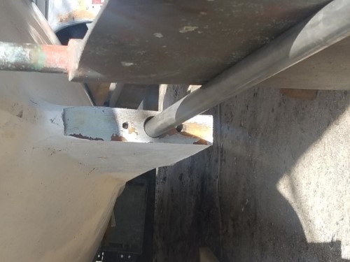
Today's progress was surgery related. Cut the aft keel section, do some test fitting and grinding. Looks good. Much less complicated than I was afraid it would be. Have gallons of vinylester resin and lots of woven, cloth, and mat. Hopefully the resin is still good, will test a small batch first...
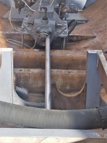
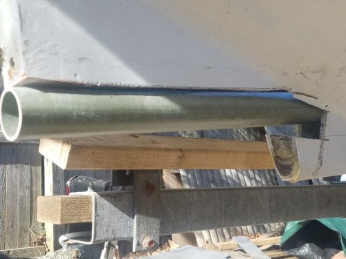
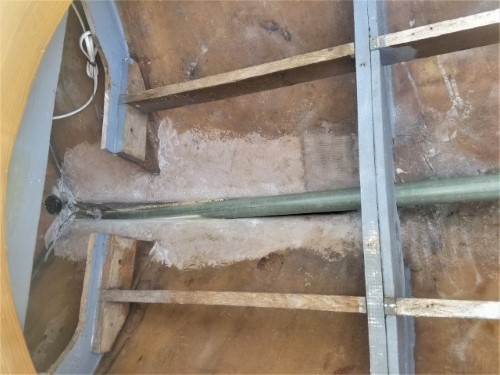 |
    
narrabay2
Advanced Member
Username: narrabay2
Post Number: 42
Registered: 10-2019
| | Posted on Sunday, May 03, 2020 - 04:35 pm: | 


|
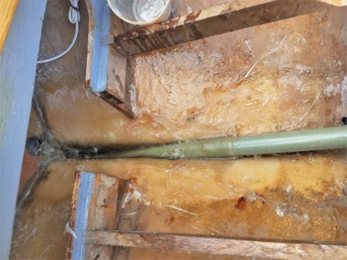
More progress. Fiberglass is sticky, smelly, and uncooperative... but there's nothing else like it for the purpose!
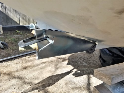
 |
    
narrabay2
Advanced Member
Username: narrabay2
Post Number: 44
Registered: 10-2019
| | Posted on Friday, May 08, 2020 - 11:16 am: | 


|
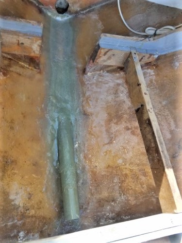
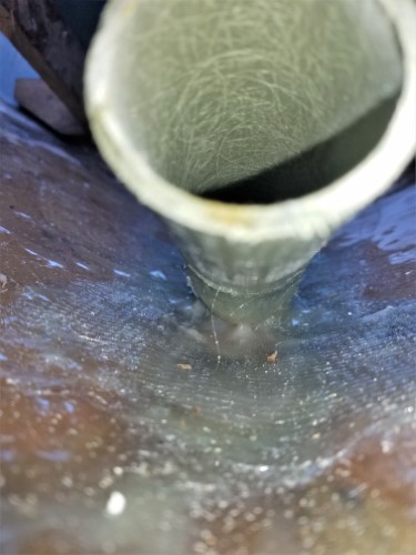
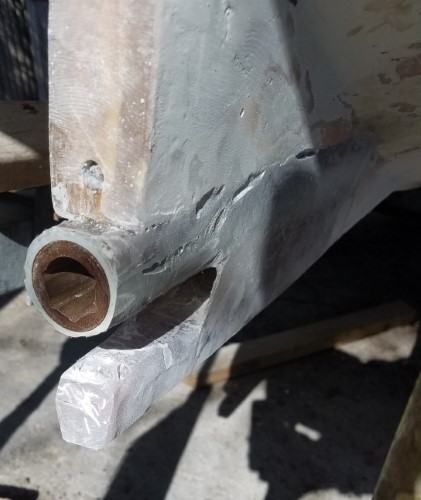
a little more progress. the inside glasswork is pretty much done. prob just one wrap of cloth on the propshaft tube to the end where the stuffing box hose attaches.
as to the rudder knee bracket gaps, it was padded with wood on back and bottom. but I may fill the gap this time with glass, not sure yet.
once this phase is finished, onto making the YT's engine bed.
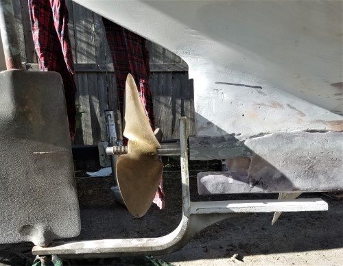
|
    
narrabay2
Advanced Member
Username: narrabay2
Post Number: 45
Registered: 10-2019
| | Posted on Friday, May 08, 2020 - 11:27 am: | 


|
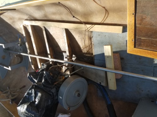 |
    
narrabay2
Advanced Member
Username: narrabay2
Post Number: 46
Registered: 10-2019
| | Posted on Sunday, May 10, 2020 - 06:38 pm: | 


|
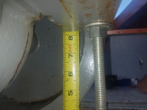
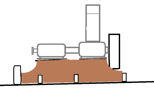
Today made good progress. The big carriage bolts allowed easy alignment of the engine with the prop shaft. The coupler flange looks good (my first one), shaft appears good (also a first) now making the engine bed, so, fingers crossed.
After final trimming and fitting, leaving 1/4" on the edges for fiberglass, the double 3/4" pieces now drying in the boiler room will be fiberglassed in a mold on the bench then glassed into the boat (the top will be under the engine flange which will be bolted down into it).
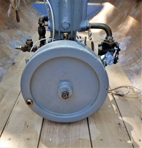
Those two heavy crossmember will be taken down to match the others for the floorboards. I do wish the flywheel wasnt 1" off the bottom, that will come back to bite me when there's water in the bilge! I have an electric bilge pump though which will be well hidden to minimize that problem.
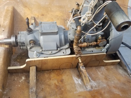
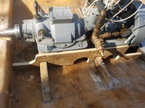
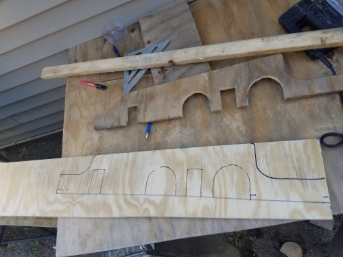
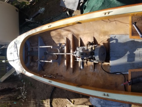
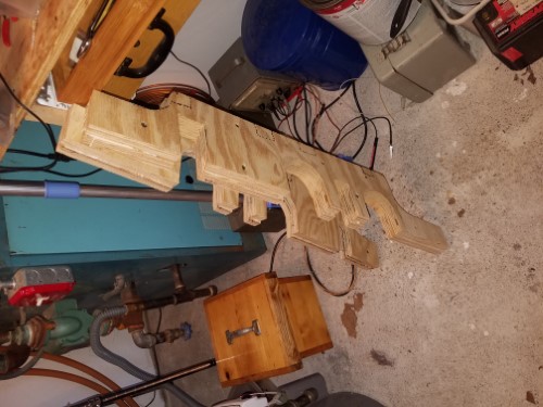
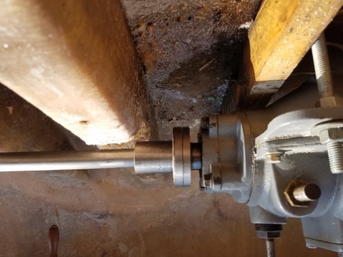 |
    
ned_l
Senior Member
Username: ned_l
Post Number: 218
Registered: 08-2012
| | Posted on Tuesday, May 12, 2020 - 10:06 pm: | 


|
Great progress!
That sounds like the best kind of growing up in Wickford. I had a similar kind of youth in the salt marshes of the Jersey shore, .... though most of our 'messing about boats' were unpowered. Great times. |
    
narrabay2
Advanced Member
Username: narrabay2
Post Number: 47
Registered: 10-2019
| | Posted on Wednesday, May 13, 2020 - 02:55 pm: | 


|
thanks ned 
a bit of a change. I decided to raise the engine higher. so, trimmed around the shaft log to release it and lifted the engine up 3" higher. now, the flywheel will be above the floorboards level. the advantage is the engine can be seen more by the curious onlooker, and will be easier to work with and work on, change the oil, and no water will get near the YT (unless some holdout jap sub commander puts a torpedo into the mix!) the prop shaft is going to be higher off the floor now, but you cant have everything. pics soon... |
    
narrabay2
Advanced Member
Username: narrabay2
Post Number: 48
Registered: 10-2019
| | Posted on Tuesday, May 19, 2020 - 02:29 am: | 


|
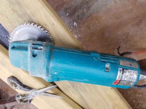
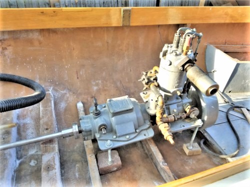
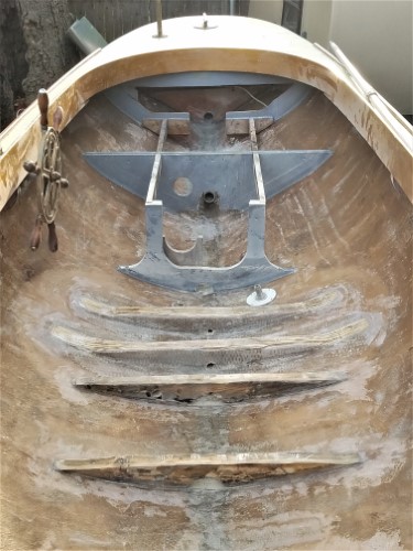
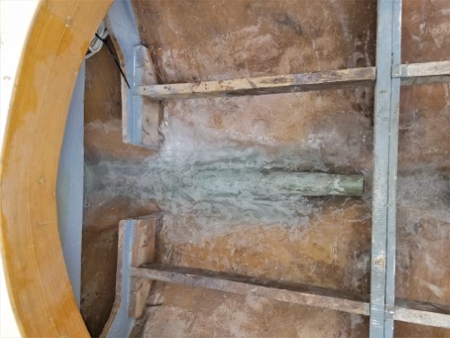
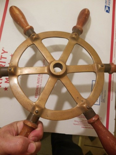
stern tube reinstalled at new angle, needs a little more sanding in places but is solid. need more glasswork on the rear keel. used the most potentially dangerous power tool in my life to lower ernie's crossmembers to approximate the others since they were for the old engine. wow were they built tough. need to glass in the old crossmembers and the tops of the ones ernie made. flywheel will now be just above the floorboards. Also found a perfect bronze or brass ships wheel on ebay that had sold for a very reasonable 25 plus shipping, boy I really missed out on that one, would have been perfect for this fantail. one conundrum I have is how to make the engine bed. I am leaning toward big oak that is finished and varnished. but not sure. Think I'd need a band saw and not even sure how to attach where it would cross the crossmember ribs. I did a search for ideas and saves some engine bed examples pics. but still not really sure. also thought about fabbing something in steel and painting with some epoxy I have.
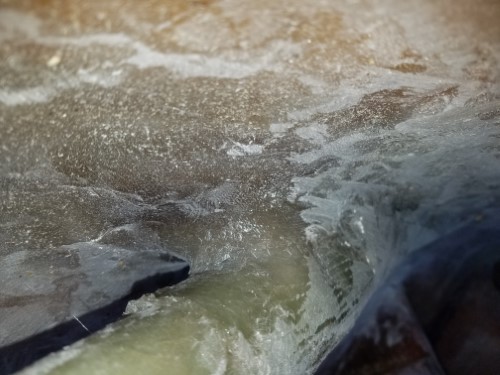 |
    
narrabay2
Advanced Member
Username: narrabay2
Post Number: 49
Registered: 10-2019
| | Posted on Tuesday, May 19, 2020 - 07:55 pm: | 


|
encased the two now-under-engine ribs and the back side of the front most rib seen with many layers of 1708 mat-backed biax, even more layers where the engine bed will attach. not pretty but strong and not too many bubbles at all. once I cap the two rear one that were cut down to match, that should be mostly it for interior fiberglassing, thankfully.
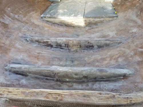
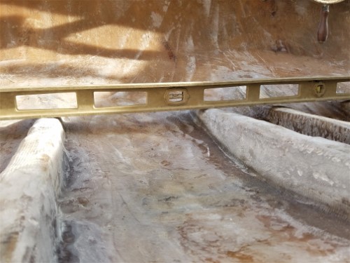 |
    
ernie
Senior Member
Username: ernie
Post Number: 2592
Registered: 01-2002

| | Posted on Wednesday, May 20, 2020 - 07:29 am: | 


|
Don't forget the limber holes. |
    
narrabay2
Advanced Member
Username: narrabay2
Post Number: 50
Registered: 10-2019
| | Posted on Wednesday, May 20, 2020 - 11:43 am: | 


|
yup. glassed them over temporarily. a die grinder with rasp bit works great for opening things like that. my compressor start capacitor died - new TemCo start and run caps arriving friday (from amazon of all places).
still trying to decide how to make engine bed, glassed plywood as before, get a bandsaw on craigslist and make oak, or weld up angle iron trusses and epoxy paint them. kind of like the steel option as long as it is attractive design... |
    
chris_spring
Advanced Member
Username: chris_spring
Post Number: 40
Registered: 02-2019
| | Posted on Thursday, May 21, 2020 - 07:50 am: | 


|
For the engine bed, oak would be nice. Rather than buying a bandsaw, perhaps you could find someone to cut it to shape for you. It might save time and effort.
Back in the day I built a boat that required some cutting for which I did not have the proper tools. I took the stock I needed cut over to the local high school. They cut it for me during shop class, and appeared to be glad to help. No charge.
Someone out there somewhere would no doubt be happy to help you.
Cheers!
Cheers! |
    
narrabay2
Senior Member
Username: narrabay2
Post Number: 51
Registered: 10-2019
| | Posted on Saturday, May 23, 2020 - 01:21 am: | 


|
thanks chris. I think I could make a steel bed look good, but after reading your suggestion I have inquired about reclaimed lumber as well (white oak).
I realized I never added that picture of the ships wheel I missed out on. maybe another one will turn up!
also, worked on the fin today. I had run out of 1708 mat backed biax cloth. so i got more, it didnt have the stitching but I figured it would work. it does distort easier, but I discovered a worse issue... when sanded, the fibers are longer (or something) and I feel like a porcupine even after a shower and using duct tape. I've applied enough of it now that there's no turning back. and I wear a tyvec suit (and respirator) but the fibers get inside the suit anyway. only during these miserable times it really would be nice to have wood boat and the skills to work with wood.
BTW this is a great channel (local to me) with series on wood boat building, start to finish, by a multi-generation boat builder.
https://www.youtube.com/user/TipsfromaShipWright/videos
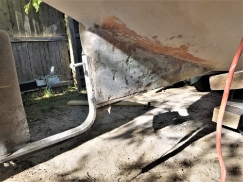
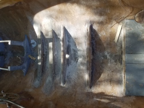 |
    
narrabay2
Senior Member
Username: narrabay2
Post Number: 52
Registered: 10-2019
| | Posted on Sunday, May 24, 2020 - 03:43 pm: | 


|
Well look what the cat dragged in. Stumbled onto a Craftsman 12" band saw for 60 that has a metal and a wood blade.
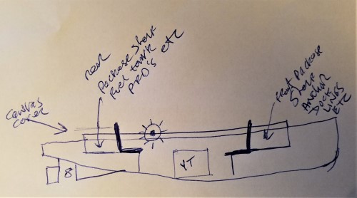
Also, finally after looking at Dispro pictures for seating ideas, and knowing I MUST have back support, figured out an interior and seating plan that accomplishes a lot of good things. Can seat 4 facing each other. Front seat will make a good rowing station in the unlikely event that is needed.
There will be a recessed "package shelf" behind both front and rear seats at seat level well below the gunwales.
Below that package deck can stuff old dock foam in case of an issue. The portable 3 gal fuel tank can be on the rear package deck for gravity feed. I can have some old school canvas covers made to stretch over them to hide the PFD,s, fire ext, and all that required stuff.
One 10ft sheet pf 3/4 marine ply would make everything and stain and varnish pretty good. But i also requested pricing on reclaimed wood planks which would be much better looking but harder to make.
Also, the flooring will be some kind of 3/4 planking and the engine bed can bolt thru that into the newly reinforced crossmembers.
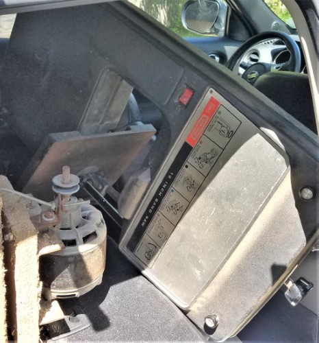
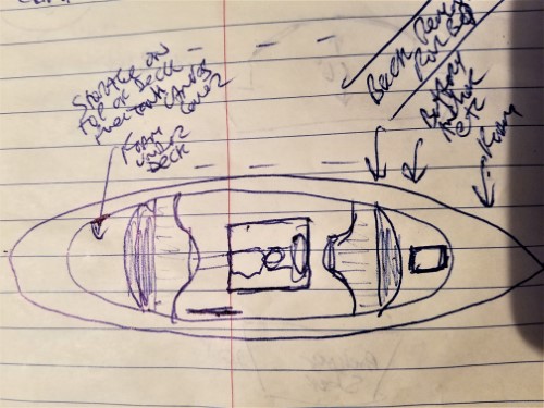 |
    
narrabay2
Senior Member
Username: narrabay2
Post Number: 53
Registered: 10-2019
| | Posted on Sunday, May 24, 2020 - 03:53 pm: | 


|
 |
    
miro
Senior Member
Username: miro
Post Number: 1081
Registered: 11-2001

| | Posted on Monday, May 25, 2020 - 09:50 am: | 


|
I agree with what you had to do, to raise the level of the engine bed.
I did not have that option on my fantail, and last year, on a rough crossing - 3-4 ft cross-wind swells - there was quite a bit of water that splashed into the boat.
The fantail hull shape is definitely NOT a "dry" boat.
Enough water got in that when I slowed down coming into the dock and the boat leveled out, the bilge water flowed forward and was launched heavenward, by the flywheel.
Luckily it was a warm day, so I did not mind getting wet. There's about 1 in clearance to the hull from the flywheel.
So now I am designing a builtin bilge pump arrangement that will reach back into the narrow stern area and get rid of the bilge water while I'm running.
Miro |
    
narrabay2
Senior Member
Username: narrabay2
Post Number: 55
Registered: 10-2019
| | Posted on Tuesday, June 02, 2020 - 08:13 pm: | 


|
Miro you maybe could make a copper tray for under the flywheel to keep the water out?
as to my project, I think the first draft of interior floors and seats will be pine. even that will cost about $150 plus the varnish and stain.
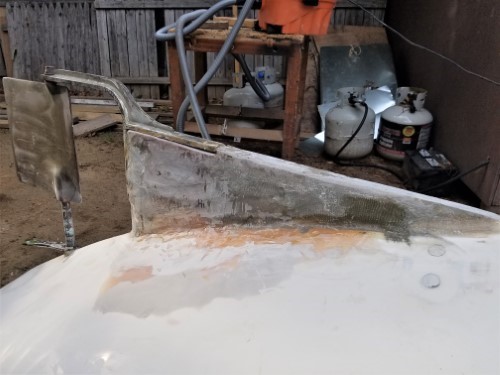
been working on the fin. I was able to turn the boat over. it went smoothly except minor damage to the coaming wood from the chain hook (cant see everything happening when working alone)
the fin is complete structurally but needs "bodywork". I am NOT good at that, but wil try. Not even sure what to use for filler. I have a bag of micro-balloons, maybe use that and then a board sander?
as a last resort, I can simply take comfort that this part of the boat is below the waterline!
 |
    
narrabay2
Senior Member
Username: narrabay2
Post Number: 56
Registered: 10-2019
| | Posted on Wednesday, June 03, 2020 - 03:53 pm: | 


|
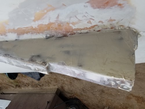
Micro-balloon and vinyl ester resin mixed becomes body filler, and it sands easily... (wear respirator when mixing and sanding)
 |
    
narrabay2
Senior Member
Username: narrabay2
Post Number: 57
Registered: 10-2019
| | Posted on Wednesday, June 03, 2020 - 08:09 pm: | 


|
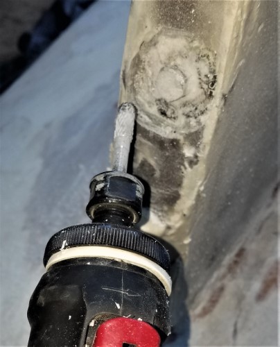
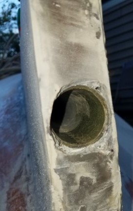
removing the rubber expanding plug sourced from auto parts store.
 |
    
narrabay2
Senior Member
Username: narrabay2
Post Number: 61
Registered: 10-2019
| | Posted on Saturday, June 06, 2020 - 04:31 pm: | 


|
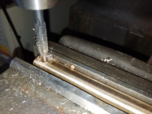
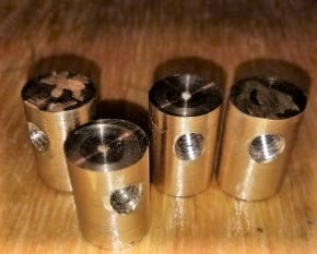
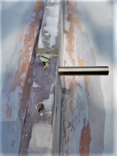
Time to attach the knee. Another thing I never did before. Used an old bronze prop shaft piece that ernie gave me to make the nuts. Will bed them in something to seal them in. Didnt want to use stainless due to crevice corrosion and dissimilar metals. The flat head machine screws are brass, bolts silicon bronze as is presumably the rudder knee. I think those are not too dissimilar anyway. This was not a precise operation but did the best I could

 |
    
narrabay2
Senior Member
Username: narrabay2
Post Number: 62
Registered: 10-2019
| | Posted on Saturday, June 06, 2020 - 04:32 pm: | 


|
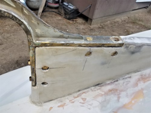 |
    
chris_spring
Advanced Member
Username: chris_spring
Post Number: 48
Registered: 02-2019
| | Posted on Sunday, June 07, 2020 - 07:32 am: | 


|
Clever! That ought to do it.
Cheers! |
    
narrabay2
Senior Member
Username: narrabay2
Post Number: 63
Registered: 10-2019
| | Posted on Sunday, June 07, 2020 - 07:39 pm: | 


|
bedded the knee in fiberglass chopped strand mix to fill the low area at the front, then when that cured, sealed with silicone caulking before bolting down for good. could use a bit more body work, next year.
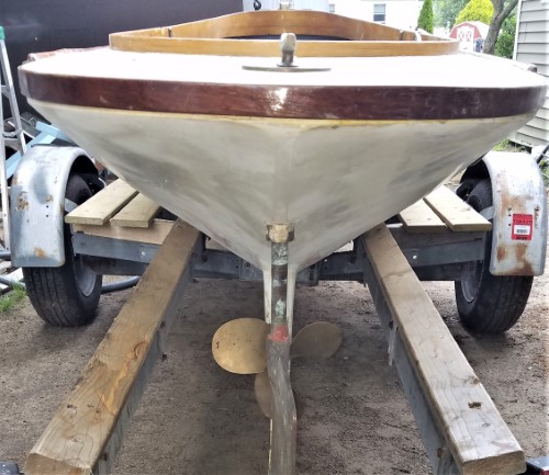
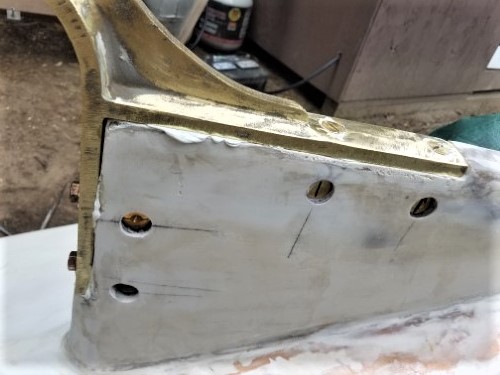
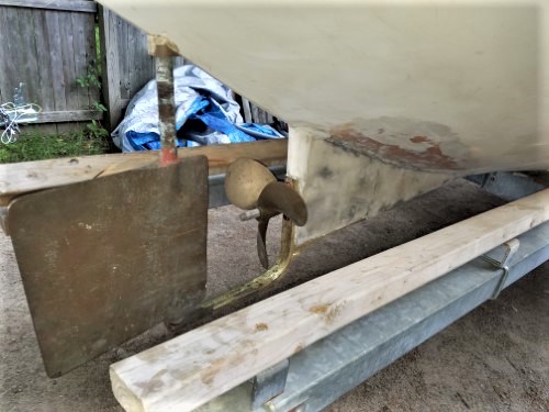 |
    
narrabay2
Senior Member
Username: narrabay2
Post Number: 64
Registered: 10-2019
| | Posted on Sunday, June 07, 2020 - 07:41 pm: | 


|
seal up the internal bronze nuts
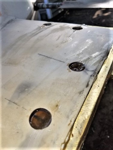
and up to go back on the trailer
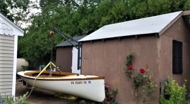 |
    
narrabay2
Senior Member
Username: narrabay2
Post Number: 65
Registered: 10-2019
| | Posted on Wednesday, June 10, 2020 - 11:23 am: | 


|
Found a source for local white oak 1" thick, dried. Will be making the floors and seats out of that. Still figuring out the engine bed material choice. |
    
narrabay2
Senior Member
Username: narrabay2
Post Number: 66
Registered: 10-2019
| | Posted on Saturday, June 13, 2020 - 03:16 pm: | 


|
Couple pics in case anyone is watching this progress. Mixed two colors of rustoleum with some hardener. Second coat will need to have more almond. Picked up some air dried native white oak, planed smooth one side. Some boards not perfect (wavy) but we'll see how it goes starting with flooring and then some type of an engine bed. But at least the prop shaft/ inside stuffing box project is pretty close to done.
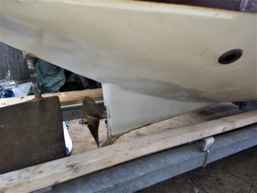
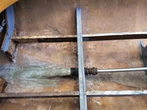
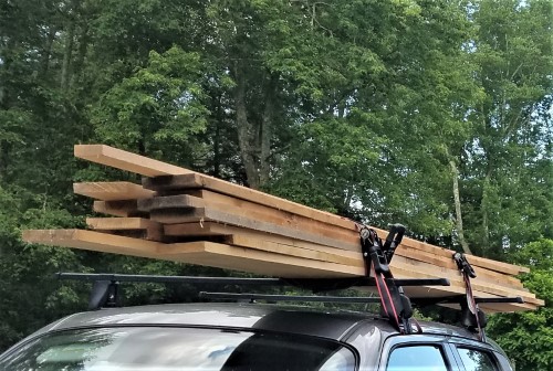 |
    
narrabay2
Senior Member
Username: narrabay2
Post Number: 67
Registered: 10-2019
| | Posted on Saturday, June 13, 2020 - 08:25 pm: | 


|
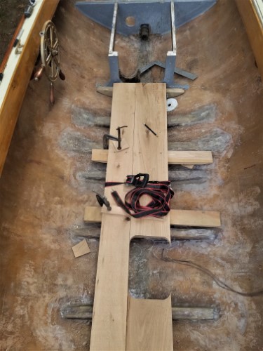 |
    
chris_spring
Advanced Member
Username: chris_spring
Post Number: 49
Registered: 02-2019
| | Posted on Sunday, June 14, 2020 - 05:28 pm: | 


|
If those are 1" oak, they'll be pretty substantial floorboards. I used 1/2" in the Gidley. I left about 1/4" space between each board to allow water to flow through them into the bilge, and to allow for swelling of the planks.
Cheers! |
    
narrabay2
Senior Member
Username: narrabay2
Post Number: 68
Registered: 10-2019
| | Posted on Sunday, June 14, 2020 - 08:36 pm: | 


|
thanks chris. they are about 7/8" white oak, pretty thick. never did this before and its now a race with time so as not to miss the boating season. lot to do fitting the YT etc. they are glued and screwed to their own oak cross pieces so the whole deck can be screwed down in a few places to the boats ribs and it will be removeable if needed. the center forward plank is not glued for bilge access. made that rear seat from plywood to test the shape. the seat back will be oak. not sure if I want to so anything in the front as yet, may just find a steamer trunk for the pfd's etc and set that in the front area for this year.
one thing undecided is how to preserve and seal the oak. I know white oak is naturally sealed anyway but need to finish it with something as well, I would think. varnish, oil, still figuring that out. has to be fast and affordable.
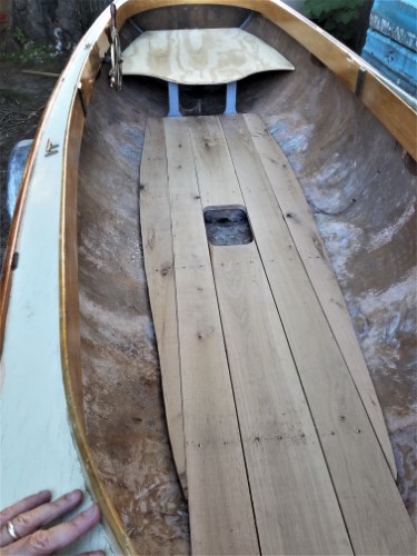 |
    
narrabay2
Senior Member
Username: narrabay2
Post Number: 69
Registered: 10-2019
| | Posted on Sunday, June 14, 2020 - 08:41 pm: | 


|
all manner of clamps and straps to pull things where they needed while the titebond III cured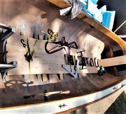 |
    
chris_spring
Advanced Member
Username: chris_spring
Post Number: 50
Registered: 02-2019
| | Posted on Monday, June 15, 2020 - 06:46 am: | 


|
WRT finish on the oak. It depends on what you want and like. The only thing to be aware of will be traction. If you don't mind colour, try an enamel like Tremclad. If not put on too heavily it will seal the wood while not becoming too slippery when wet. If it is, add a coat of paint, then sprinkle sand over it while wet. Once dry, vacuum off the excess sand and paint again. For a natural finish, Tung Oil might work. The beauty of Tung Oil is that it is easy to apply, and if the wood gets marked or scratched just touch it up with more Tung Oil.
My $0.02 CDN.
Cheers! |
    
miro
Senior Member
Username: miro
Post Number: 1083
Registered: 11-2001

| | Posted on Monday, June 15, 2020 - 02:48 pm: | 


|
You can try a matte varnish or paint for the flooring. But I think you'll find that after some use , whatever you use will show wear and become less slick - and that's OK because you'll be using the boat and messing around in it. In reality, you don't walk around all that much in the boat when you are cruising.
Next time I'm at my camp, I'll take a picture of how close my flywheel is to the hull. You'll appreciate the work you've done to raise the engine.
Looking good . . . .
miro |
    
narrabay2
Senior Member
Username: narrabay2
Post Number: 70
Registered: 10-2019
| | Posted on Monday, June 15, 2020 - 03:59 pm: | 


|
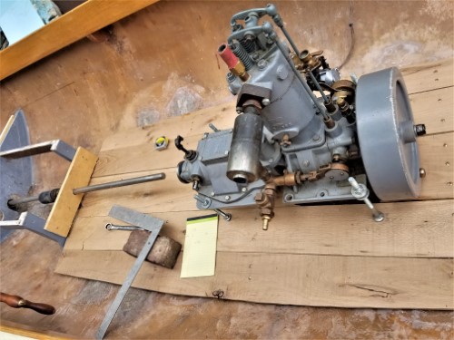
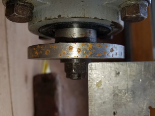
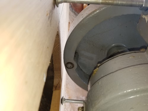
Thanks guys. Miro, as to engine height, today I started pre-aligning the engine and the thickness of the flooring wasnt considered. I have 1/2" under the flywheel to the top of the floor board. And that was moving the engine 6" farther forward (which leaves the propeller shaft too short but I can make a longer coupling). This is what happens when trying to wing it! The short clearance will affect knuckles if hand starting. What I plan to do is either cup that end of the plank or make that piece removable with a finger hole, just pop it back in when she starts. I have the cub cadet starter bracket made and can install that anyway, so manual start would be only a rarity. Plus an old leather "starting glove" on hand wouldnt hurt either!
I cheated the prop shaft up about 1/8" at the stern tube which should be fine, that gave almost the 1/2 at the flywheel. The boat crossmember are thick imprecise fiberglass, if I take down the high spots the floor will drop a little more. It all adds up! So, it is doable now and the engine is above the floor planks. Wish I had another 1/2" but no use crying over spilt milk now.
Oh yeah, it's also a good thing I didnt attach the oak flooring assembly to the boat yet, aligned it to the prop shaft. Visually things really should line up.
Engine is at about a 5 degree angle to the keel.
 |
    
narrabay2
Senior Member
Username: narrabay2
Post Number: 71
Registered: 10-2019
| | Posted on Tuesday, June 16, 2020 - 10:03 pm: | 


|
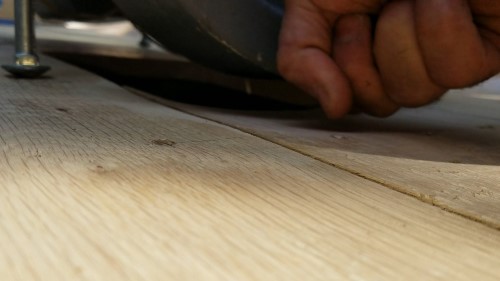
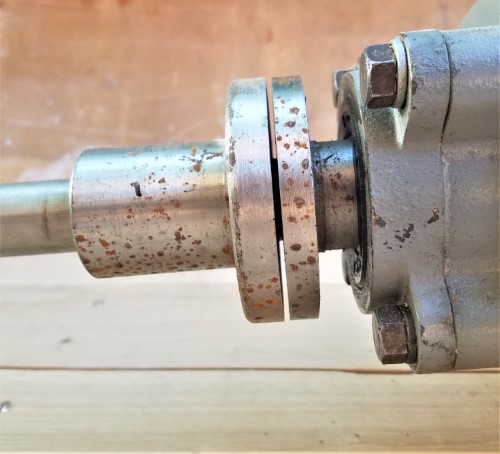
took the crossmember ribs down a bit (remove high spots) made sure the flooring wasnt resting on the edges. the monster dewalt 9" 5.3hp grinder with a 24 grit disk helped. that thing is the second most dangerous implement in my shed.
 |
    
narrabay2
Senior Member
Username: narrabay2
Post Number: 72
Registered: 10-2019
| | Posted on Tuesday, June 16, 2020 - 10:11 pm: | 


|
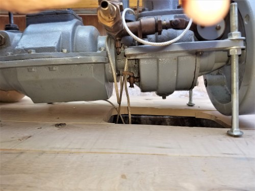
one issue is that I'll need to get at the bilge and oil drain etc. with wood engine bedding, how does anyone access those things? a steel frame engine bed arrangement (epoxy painted, and someone gave me a gallon of marine epoxy coating) may be a better option for underneath access. I just dont ever see that done. did find a source for 2-1/4 slabs of air dried white oak cut to my dimensions for $50 if I want. I suppose I could hole saw a 3" hole in the side to reach the oil drain. the drip oiler always adding oil so Ernie IIRC told me remove the overage from the little brass drain in the bottom. with a traditional wooden bed, now way to reach it. I guess I could extend it with a copper tube but if that ever failed while running, not good for this rare engine.
 |
    
narrabay2
Senior Member
Username: narrabay2
Post Number: 73
Registered: 10-2019
| | Posted on Thursday, June 18, 2020 - 06:47 pm: | 


|
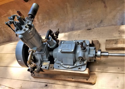
repurposed the engine bed that ernie sold me with the YT. that buys me all the time to find some nice fancy hardwood later. amazing how much tapping, jiggling, etc to get everything lined up not to mention the engine sliding down the engine bed! was very helpful to be able to move the flooring too and try to get everything centered. always checking the coupling. if anything the engine might be 1/8 to 3/16 high. I can shave that from the top of the engine bed which isnt perfect due to having a cheap flimsy table saw which is about to become the anchor.
now everything comes back out to get a coat or two of varnish on the flooring, install the relocated water intake thru hull, etc. then bolted back in and start solving the rest of the issues like cooling and exhaust routing and who knows what else. 
 |
    
chris_spring
Senior Member
Username: chris_spring
Post Number: 51
Registered: 02-2019
| | Posted on Friday, June 19, 2020 - 11:45 am: | 


|
The Gidley uses shims to get engine/driveshaft alignment correct. It also has a metal pan under the flywheel which provides clearance and prevents bilge water from splashing up and being thrown around by the flywheel.
A removable pan similar to that might serve the other purpose of providing access to the drain.
The Adams has a similar drain which is inaccessible. To get to it the driveshaft must be disconnected and moved back, the engine hold down bolts removed, the water intake and exhaust hoses disconnected, the exhaust system unfastened. Then the engine must be raised. That's a lot of effort to get to the drain. Fortunately I have never found it necessary to do so.
Cheers! |
    
bruce
Senior Member
Username: bruce
Post Number: 702
Registered: 07-2002
| | Posted on Saturday, June 20, 2020 - 07:04 am: | 


|
suggest using Cetol in lieu of varnish on your oak flooring ?? May be even Waterlux finish |
    
bruce
Senior Member
Username: bruce
Post Number: 703
Registered: 07-2002
| | Posted on Saturday, June 20, 2020 - 07:11 am: | 


|
be aware that the Rose hull tends to squat while under way at speed. |
    
narrabay2
Senior Member
Username: narrabay2
Post Number: 75
Registered: 10-2019
| | Posted on Saturday, June 20, 2020 - 10:05 am: | 


|
hi bruce, yes noticed that squat, quite pronounced reduction in rear freeboard. not really a big deal, but noticeable. ernie suggested moving the engine forward and I did move it quite a lot. also planning a larger battery and may put that in nose compartment, and see what it looks like at rest. if still an issue may try a small elliptical horizontal "wing" on the rear fin with an up angle, just to see. but thats later.
as to flooring, already applied the spar varnish. looks good and will get this going for this year. lot of good wood finish options but much of the woodwork is already gloss varnish , and it was easy and quick to do.
as to bilge access, I busted loose the rear center plank (it was glued) and will rely on just the screws as with the front center plank. that wont get me to the bottom of the YT but at least anything in the bilge can be retrieved etc. |
    
narrabay2
Senior Member
Username: narrabay2
Post Number: 76
Registered: 10-2019
| | Posted on Saturday, June 20, 2020 - 06:44 pm: | 


|
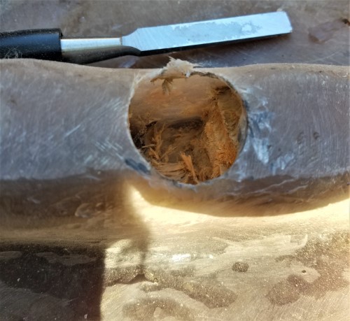
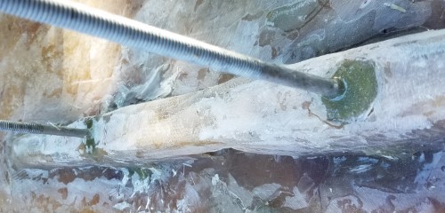
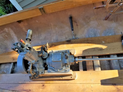
anchoring the engine. the wood in the original rib/crossmembers was just too soft. so I hollowed one out where the front transmission bolts happen to align, and filled with 1/2" chopped glass strand and a 10" carriage bolt with a bent end. drilled the engine bed and floor oak to 3/4" for adjustment. the engine really needed to come down a bit, so I worked the top of the bed best I could with limited woodworking equipment, matched them, dropped the engine down and it lined up well. I could go back up 1/8 but the flywheel still clears well enough to reach my fat fingers under it.
 |
    
narrabay2
Senior Member
Username: narrabay2
Post Number: 77
Registered: 10-2019
| | Posted on Saturday, June 20, 2020 - 06:47 pm: | 


|
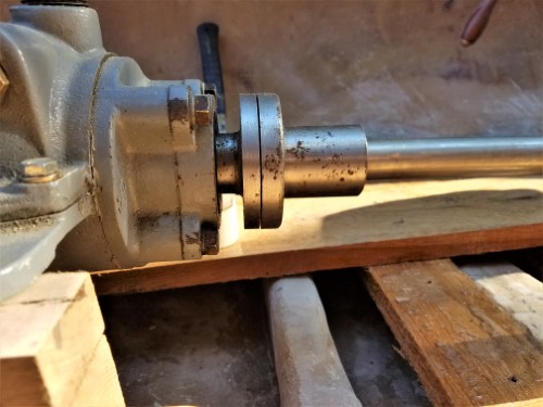
with these two main hold-down bolts, all other six can be lag-bolted thru all the way to the floor plank or just to the engine bed
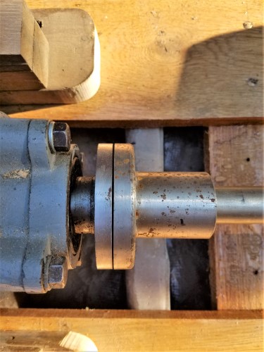
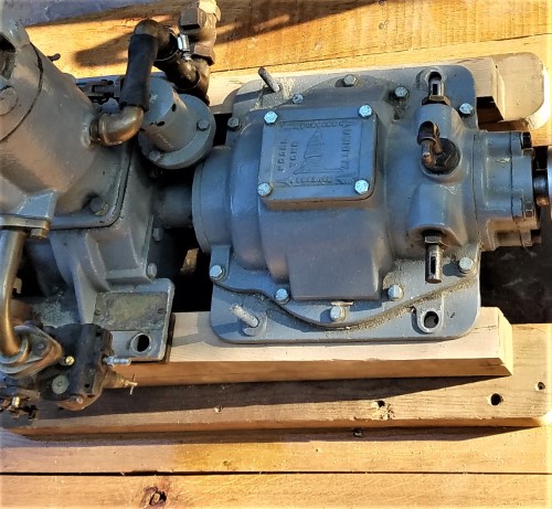 |
    
narrabay2
Senior Member
Username: narrabay2
Post Number: 82
Registered: 10-2019
| | Posted on Wednesday, June 24, 2020 - 08:39 pm: | 


|
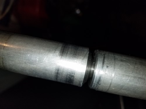
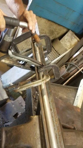
OK few pics. After moving the engine to the best position, turns out the shaft was too short. Drilled the end, and turned a short piece with a stub that was .002 bigger and pressed that in. had my buddy mig weld it, letting it cool between welds and didnt even build it up fully so as not to heat it too much. Turned the weld down on the lathe. It only had .011 runout and less once I took half the extension off to final length. Then cut the keyways. This all necessitated removing the rudder knee and rudder. I wanted to do that anyway to get some never-seize on the rudder pulley set screws and generally learn how it was put together.
Then I drilled the companion flange for 3/8 set screws, and turned the edges to a small radius for appearance. Tomorrow this should all be back together again, shaft in boat rudder back on, and will finish bolting the engine down. Also sourced a tiny Jabsco water pump for the raw water for the heat exchanger and exhaust. Need to install a small header tank for the coolant that is above the cyl head. Maybe up in/on the bow not sure. This will protect the newly sleeved cylinder and old somewhat rusted head form further corrosion. I wanted to install a keel cooler loop and use a venturi on the exhaust to get raw water just for the exhaust, but not sure how much suction a venturi would pull. That's for an engineer to determine. May play with that someday, just turna venturi section with a 1/4" nozzle and put the tube in a bucket of water and see...now for the pics
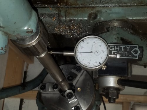 |
    
narrabay2
Senior Member
Username: narrabay2
Post Number: 83
Registered: 10-2019
| | Posted on Wednesday, June 24, 2020 - 08:40 pm: | 


|
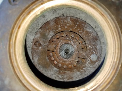
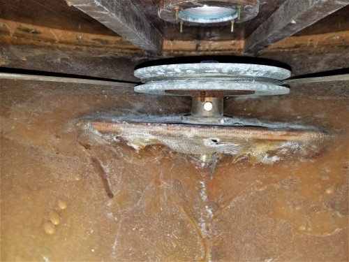
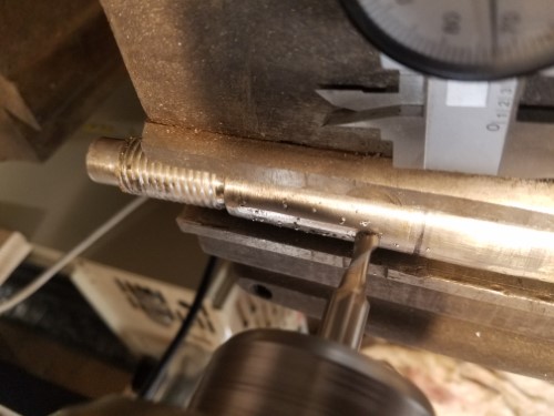 |
    
narrabay2
Senior Member
Username: narrabay2
Post Number: 84
Registered: 10-2019
| | Posted on Wednesday, June 24, 2020 - 08:41 pm: | 


|
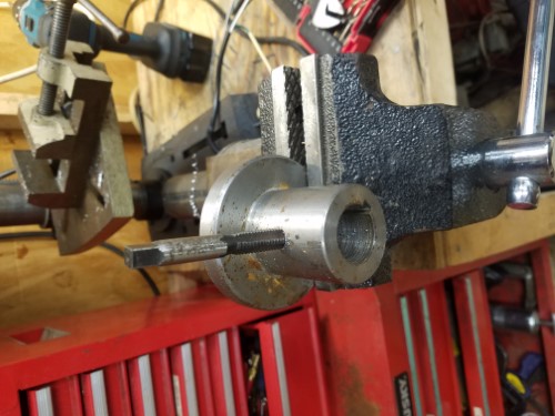
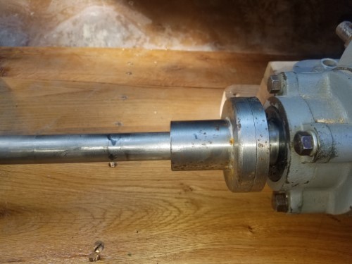
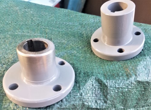 |
    
narrabay2
Senior Member
Username: narrabay2
Post Number: 85
Registered: 10-2019
| | Posted on Wednesday, June 24, 2020 - 08:44 pm: | 


|
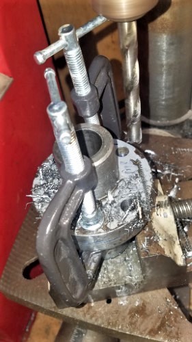 |
    
raa
Senior Member
Username: raa
Post Number: 209
Registered: 02-2007

| | Posted on Thursday, June 25, 2020 - 02:07 pm: | 


|
a Woodruff will make a much more accruate cut and a better finish for what is worth
Dick |
    
narrabay2
Senior Member
Username: narrabay2
Post Number: 86
Registered: 10-2019
| | Posted on Thursday, June 25, 2020 - 10:31 pm: | 


|
hi dick, do you mean that a woodruff cutter and make the 1-1/2" long slotted straight key slot with it? Or just use a woodruff key instead of straight? I'm not really a machinist so I dont know these things... |
    
raa
Senior Member
Username: raa
Post Number: 210
Registered: 02-2007

| | Posted on Friday, June 26, 2020 - 12:19 am: | 


|
I use the woodruff cutter to make slots as long as I need usually width of flywheel hub as a example or your prop shaft. I found conventional cutters say .250 tend to wander a bit where as a woodruff is locked into the slot its cutting.I use dark cutting oil modest speeds and feeds cut depth might be half depth or full depth and cut feeding down. Cutters are relative cheep or I can lend you one a woodruff cutter is a miniature version of the cutters used on a horizontal mill |
    
narrabay2
Senior Member
Username: narrabay2
Post Number: 87
Registered: 10-2019
| | Posted on Friday, June 26, 2020 - 01:49 am: | 


|
thanks dick for the explanation. even though the shaft is done, but for the next time this got me thinking. I had all kinds of trouble getting the taper end of the prop shaft clamped tight with the taper level to the bed, because of the weight of the shaft etc, even though I supported it. Eventually got it and cut an fairly acceptable slot.
for your suggestion, I come in from the side with the woodruff cutter? I could use tee nuts and clamp-downs to put the shaft tight to the bed with side of the taper even with the crossfeed y axis. then presumable move the x axis until it just meets and make cuts until it gets to .125" for the 1/4" keyway going by the table feed marks.
so its coming in from then side I guess. that would make things easier and you said makes a better cut. I'll try that next time. |
    
raa
Senior Member
Username: raa
Post Number: 211
Registered: 02-2007

| | Posted on Friday, June 26, 2020 - 12:22 pm: | 


|
yes you come in on the side of the shaft. Clamp in vice with small amount of shaft sicking out. Loosen vice and turn till cutter is parallel to taper check with dial indicator to check for parallelism
Send me a email and I will send you some pictures
for whats its worth
Dick |
    
narrabay2
Senior Member
Username: narrabay2
Post Number: 90
Registered: 10-2019
| | Posted on Wednesday, July 01, 2020 - 09:18 pm: | 


|
took a bit longer than anticipated, but nice to see a home made companion flange, home made propeller shaft, home made shaft tube conversion to inside stuffing box all coming together!
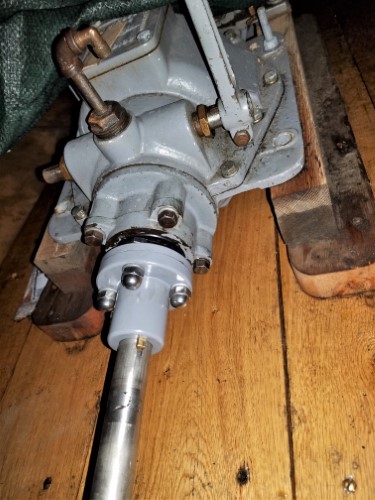
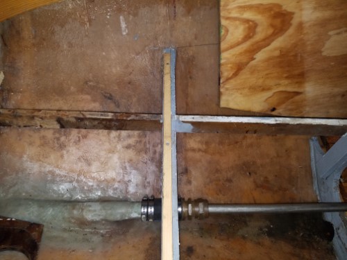
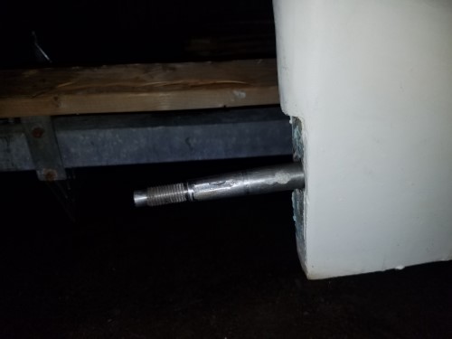 |
    
narrabay2
Senior Member
Username: narrabay2
Post Number: 92
Registered: 10-2019
| | Posted on Saturday, July 04, 2020 - 08:24 pm: | 


|
and, the pretty much finished result out back. "body work" isnt exactly perfect, but not bad either, and that's a project for next year...
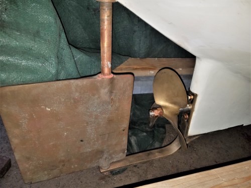 |
    
chris_spring
Senior Member
Username: chris_spring
Post Number: 55
Registered: 02-2019
| | Posted on Sunday, July 05, 2020 - 06:45 am: | 


|
Well done! It will be nice to have it back in the water. I hope all goes well.
Cheers! |
    
narrabay2
Senior Member
Username: narrabay2
Post Number: 93
Registered: 10-2019
| | Posted on Wednesday, July 08, 2020 - 05:12 pm: | 


|
Thanks Chris always nice to hear some positive feedback!
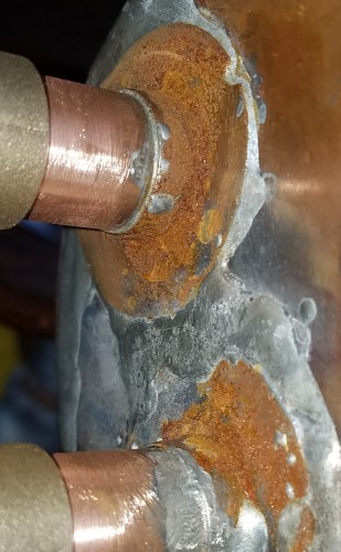
It was time to deal with the cooling issue. This YT cannot see raw water. It also cannot have any cooling system pressure or the water jacket will split.
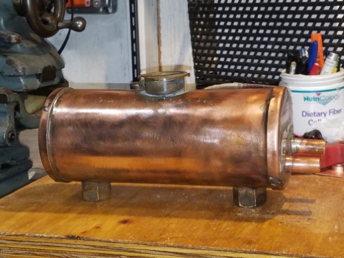
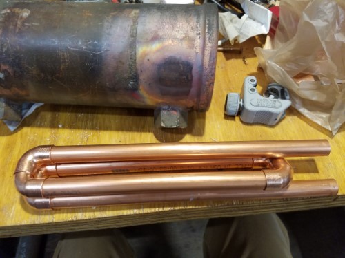
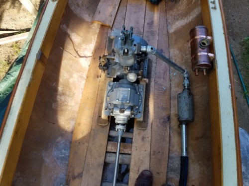
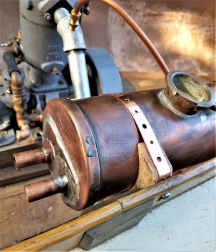
So I came up with this heavy copper header tank about 10" x 4.5" diameter, and added about 40" of 1/2" copper tube.
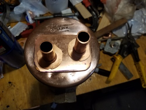
The engine's cooling pump will move coolant around and through the tank in/out those bottom fittings.
The little Jabsco will move sea water through that tubing and then into the exhaust just after the engine. That should exchange the heat nicely.
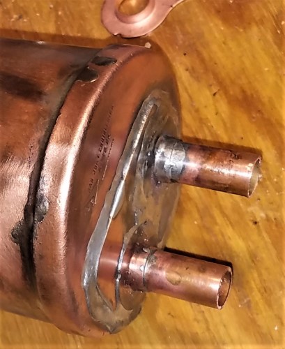
Based on some advice, the flanges were silver soldered for strength but everything else was lead soldered, using a mini oxy-acetylene on low temp.
This wont win any shows, and hasnt been pressure tested yet, but I think it will be fine.
Looking for ideas to mount it to the starboard gunwale adjacent to the YT on the exhaust side. Maybe hardwood cradle hooks and 2 straps? Later I may have a radiator shop add a Model A filler neck so I can use a nice brass screw on cap.
 |
    
narrabay2
Senior Member
Username: narrabay2
Post Number: 94
Registered: 10-2019
| | Posted on Wednesday, July 08, 2020 - 08:13 pm: | 


|
closeup of the not-that-pretty but I think solid soldering. first time for something like this...
 |
    
chris_spring
Senior Member
Username: chris_spring
Post Number: 56
Registered: 02-2019
| | Posted on Thursday, July 09, 2020 - 06:43 am: | 


|
I am curious to see how this works out.
good luck!
cheers! |
    
raa
Senior Member
Username: raa
Post Number: 212
Registered: 02-2007

| | Posted on Thursday, July 09, 2020 - 11:03 am: | 


|
sure looks professional to me
Cheers
Dick |
    
narrabay2
Senior Member
Username: narrabay2
Post Number: 95
Registered: 10-2019
| | Posted on Thursday, July 09, 2020 - 11:12 am: | 


|
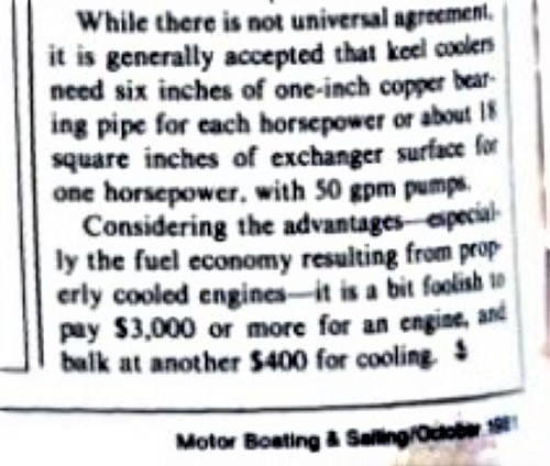
According to this site https://betamarine.co.uk/keel-cooling-calculations/, I need:
Engine bhp � 5 = area in square feet
2hp / 5 times 144 = 57 square inches
Another source mentions 18 sq in per hp, or 36 square in total for this Palmer.
This setup has more than 67 sq inches, plus the outside of the tank will shed some heat.
I did find this but the Fantail wont be run for many hours and is trailered. Plus this would be easy to fix if needed. But in compiling this post, I found the solder can dissolve... I wonder where I'd even add a zinc to stop that alleged solder dissolving problem, inside the end of a tube?
"If you plan to run in salt water then there are a few issues. I have used copper in salt water and the tin in the solder is disolved right away. Like in days as it's not very noble and hte copper is. Zincs will of course help."
Hopefully the little Jabsco 1/4" moves enough seawater. If not, I do have a somewhat larger Jabsco on the shelf to swap.
Yes, it will be neat to see how this works, how warm the seawater comes out of the coil, what temp the engine runs at , etc
I'm looking for an old brass boiler gauge to mount under the tank to see the engine water temp before it is cooled (engine temp). But thats just for fun...
 |
    
narrabay2
Senior Member
Username: narrabay2
Post Number: 96
Registered: 10-2019
| | Posted on Thursday, July 09, 2020 - 03:44 pm: | 


|
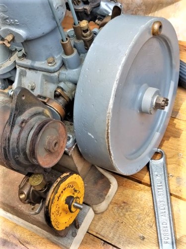
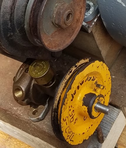
now working out mounting the pedestal pump. made a stainless bushing to fit a fairyman pulley to it. I cant find any examples on here or google of a mounted pedestal pump and I suspect they are not meant to be pulley driven. (?) that belt tension would put a lot of leverage on those two pump feet way back from the pulley.
If anyone here has a mounted pedestal pump it would be nice to see a picture...
thank you
 |
    
narrabay2
Senior Member
Username: narrabay2
Post Number: 97
Registered: 10-2019
| | Posted on Friday, July 10, 2020 - 07:52 pm: | 


|
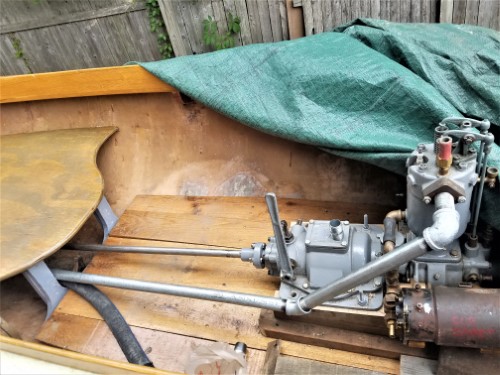
Picked up up some 1" galvanized iron pipe for the exhaust. Everything getting so expensive! The cast iron silencer is under the seat and rubber hose from there out the back as Ernie had it. Raw water will go in at the first elbow. Not sure if the pipe will still need to be wrapped... (is *that* expensive too? probably!). Maybe the exhaust should just go out the side like a Dispro?
May be able to mount the jabsco pump to the back of the starter generator, more on that later...
 |
    
narrabay2
Senior Member
Username: narrabay2
Post Number: 98
Registered: 10-2019
| | Posted on Saturday, July 11, 2020 - 12:27 pm: | 


|
Ok, well this was much easier than I thought and when I make the bracket, if there is any runout I will incorporate either a small flex coupling or mount the pump to rubber feet. May try a set screw, or weld a stub extension to the armature shaft which would be located by this 3/8" center hole. I may take out the field coils so I can mig weld a nice custom pump mounting bracket to that thick steel s-g housing. Then I can wire brush everything and paint with epoxy primer and then enamel.
IF I had real skill, I would like to cast a new bronze rear cover for the S-G with a pump impeller cavity built right in, now THAT would be slick... may try and find a foundry and take a shot at that.. why not?
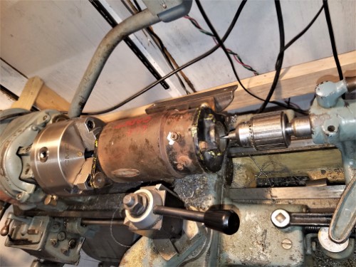
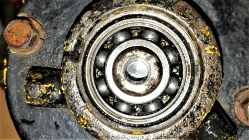
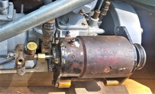 |
    
narrabay2
Senior Member
Username: narrabay2
Post Number: 99
Registered: 10-2019
| | Posted on Saturday, July 11, 2020 - 12:27 pm: | 


|
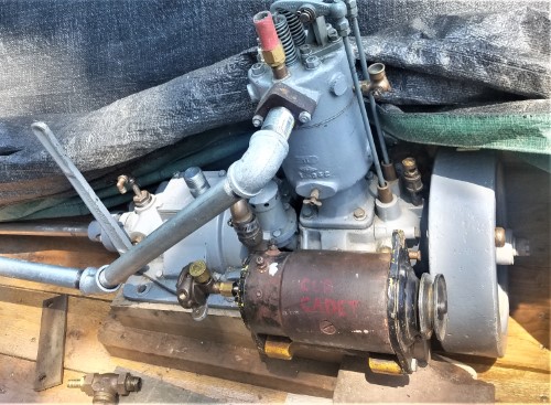
the engine flange sits about 1/4" higher than the transmission flange so it was easy to replace that oak shim with the angle starter bracket... did that last year. it spins the YT nicely and now will keep the ships battery topped up.
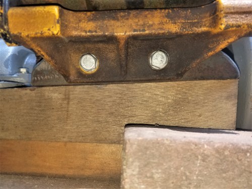
 |
    
narrabay2
Senior Member
Username: narrabay2
Post Number: 100
Registered: 10-2019
| | Posted on Saturday, July 11, 2020 - 07:35 pm: | 


|
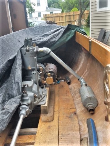
better exhaust layout... may keep it this way... thats 1" pipe to the muffler (union in front of muffler)... 1-1/2" hose after muffler. water will go in just after the 45 up top
 |
    
narrabay2
Senior Member
Username: narrabay2
Post Number: 103
Registered: 10-2019
| | Posted on Friday, July 17, 2020 - 11:20 am: | 


|
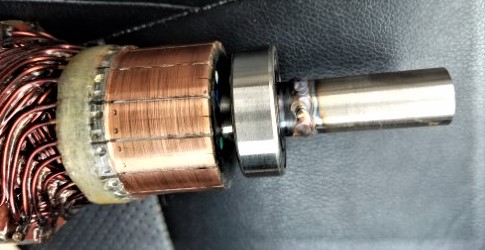
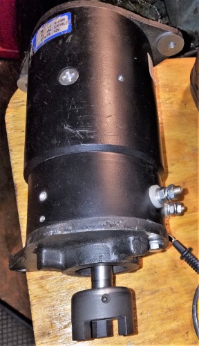
Working on starter-generator-pump...bout to get shaft extension tig welded. Its inserted by an interference fit stub. Hoping for < .005" run out, but the Lovejoy coupling should introduce sufficient forgiveness in any case.
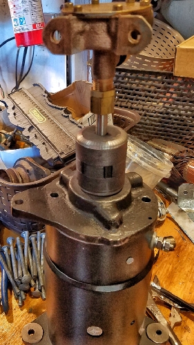
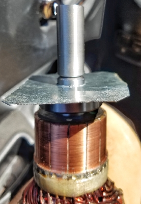
The tin piece is to protect the bearing. |
    
narrabay2
Senior Member
Username: narrabay2
Post Number: 104
Registered: 10-2019
| | Posted on Friday, July 17, 2020 - 10:26 pm: | 


|
Friend tig welded, and I turned it. Not perfect, but it should suffice... now to make a bracket for the pump. Fortunately, these starter generators have a vary thick steel outer body that can be welded to, or drilled and tapped easily.
 |
    
chris_spring
Senior Member
Username: chris_spring
Post Number: 59
Registered: 02-2019
| | Posted on Saturday, July 18, 2020 - 07:03 am: | 


|
Watching. Very cool! I completely missed that it was a starter generator. I figured it was a generator. The Gidley exhaust is galvanised pipe as well. The Adams puts out 2 1/2 hp. It would be marginal without water cooling for the exhaust. It doesn't need much, but otherwise the pipe gets pretty hot for a fair distance back, enought to burn skin if contacted.
Cheers! |
    
narrabay2
Senior Member
Username: narrabay2
Post Number: 105
Registered: 10-2019
| | Posted on Saturday, July 18, 2020 - 12:29 pm: | 


|
thanks chris, all the flare and plumbing fittings showed up, so today i will start the water runs. I think I may use the Jabsco for coolant and the YT pump for the raw water thru the loop and into the exhaust. also, the cyl head seems to keep getting rust flakes and crumbs. I vacuumed them out as much as I could. the 3/8 fitting doesnt have much room below inside the water jacket and I dont want it to suck in a crumb and clog. so I may make a strainer out of ss screen and some jb weld into the fitting. and also, try and create a sight glass where the engine water enters the tank to see that it is flowing. maybe a 2" glass tube on the filler neck like a drip oiler, anything see see the coolant flowing... there are also old school coolant flow meters that basically spin, I've seen. this should start coming together now hopefully, for sea trials eventually... |
    
narrabay2
Senior Member
Username: narrabay2
Post Number: 106
Registered: 10-2019
| | Posted on Saturday, July 18, 2020 - 10:50 pm: | 


|
Got the exhaust piping all torqued, never seize on the silencer threads. Started with the copper tubing, starting with the exhaust water injector per Ernie's method.
Having trouble getting the exhaust hose onto the 1.5" pipe beyond where it was already expanded, even using soap. Maybe warm it up?
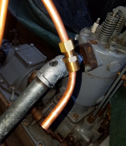
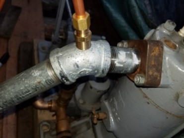 |
    
chris_spring
Senior Member
Username: chris_spring
Post Number: 60
Registered: 02-2019
| | Posted on Sunday, July 19, 2020 - 06:51 am: | 


|
On the Adams, water enters slightly lower down on the exhaust. I suspect that is to provide a slight venturi effect and to ensure no water finds its way to the crankcase via the exhaust port after the engine has been shut down.
cheers! |
    
miro
Senior Member
Username: miro
Post Number: 1088
Registered: 11-2001

| | Posted on Sunday, July 19, 2020 - 10:01 am: | 


|
One way that DisPro folks use to make sure cooling water is flowing, is to use a clear hose on the inlet, .
You can usually see bubbles coming through.
The water outlet port in the exhaust manifold on the St Lawrence, is just above the gas exhaust port.
So far have never had any water into the engine.
Haven't heard of any DisPro folks who have a St Lawrence in their boat, report that either.
Soon, you'll have it running and all will be rewarded for all of your work.
miro |
    
dick
Advanced Member
Username: dick
Post Number: 42
Registered: 07-2004
| | Posted on Sunday, July 19, 2020 - 11:04 am: | 


|
I too am looking forward to seeing it out on the water and rewarding you for all your hard work and ingenuity over so many months.
Dick |
    
narrabay2
Senior Member
Username: narrabay2
Post Number: 107
Registered: 10-2019
| | Posted on Sunday, July 19, 2020 - 07:24 pm: | 


|
Thanks guys. "90% done and 50% to go" as they say! Today mounted the header tank to the inside of the coaming. The top fasteners will be replaced with bronze. The straps are copper plated steel home depot pipe hangars. They too can be replaced later with thick copper strap (if that's appropriate). Also bought a cheap garden hose for the shop dehumidifier, and was able to cut and use that to test the raw water coil for leaks, and it passed. Not a drop inside the tank. Then the S-G-P bracket was cleaned in a bucket of gasoline, wire brushed, and then painted. No fancy epoxy primer like when I disassembled, sandblasted and cosmetically restored the YT as well as full mechanical disassembly, checkout and replace rings, resleeved it, and new oil seals.
Still need to make the SGP pump bracket.
Anyway, its coming. Still need to make the rear seat-back, and build the rear-facing front seat/ rowing station. If the YT stops I want my wife to be comfortable while rowing.  haha haha
Some pics:
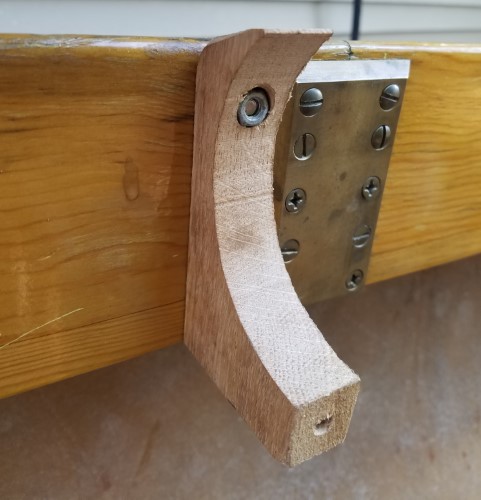
One side is done here. Both were done the same way.
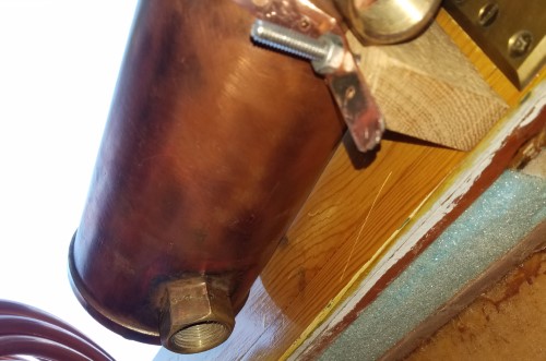
 |
    
narrabay2
Senior Member
Username: narrabay2
Post Number: 108
Registered: 10-2019
| | Posted on Sunday, July 19, 2020 - 07:29 pm: | 


|
This image shows how the strap goes behind the oak cradle, in a slot on the back of the cradle piece, and the bolt goes through the coaming, through the strap, and to the countersunk nut...
 |
    
narrabay2
Senior Member
Username: narrabay2
Post Number: 109
Registered: 10-2019
| | Posted on Sunday, July 19, 2020 - 07:31 pm: | 


|
Pressure testing. The one hose clamp on end of the plugged short hose section was deformed and leaking, but that let the air purge out of the hose and coil which made the test more effective.
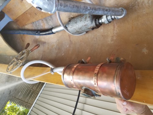 |
    
narrabay2
Senior Member
Username: narrabay2
Post Number: 110
Registered: 10-2019
| | Posted on Monday, July 20, 2020 - 08:40 pm: | 


|
Worked on the water outlet elbow. Cut it off short because it bottoms anyway and the end gets too close to the exhaust runner. Cleaned and wire brushed the inside, added a stainless steel screen using JB weld. This should keep the rust crumbs from going into the loop and getting stuck who knows where or beating up the impeller.
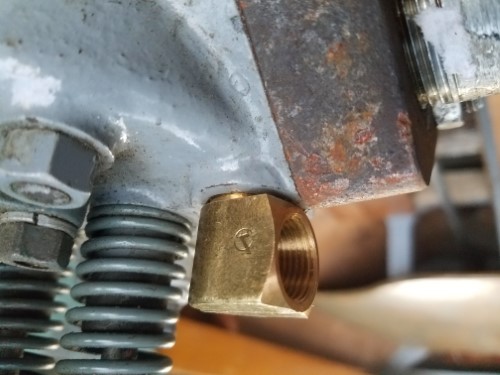
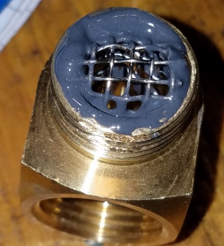 |
    
ernie
Senior Member
Username: ernie
Post Number: 2601
Registered: 01-2002

| | Posted on Monday, July 20, 2020 - 08:59 pm: | 


|
Chris,
I hate to rain on your parade...
Impeller???? Isn't this the freshwater side of things using the YT factory pump?
I would NOT suggest you use the factory YT pump for raw water. Use the Jabsco for raw water just like it was designed for. It isn't the raw water in the YT pump it is the pump flow which was designed by the original designer of the entire engine to flow the proper amount of water to properly cool the engine.
The water pump on the YT1 is positive displacement. If that screen plugs up you WILL blow the water jacket, or part of it right off the engine.
Bottom line, better to have crumblies in the heat exchanger than part of the water jacket laying in the bilge.
The simple solution is to put a filter between the exhcanger and the pump inlet and flush the exchanger and clean the filter once in a while and use the Jabsco pump for raw water like I told you a long time ago.
By the way there are hundreds of thousands of marine engines out there using the original factory pump for the fresh water side of things and a Jabsco style of pump the raw water.
Hope this helps
Ernie |
    
narrabay2
Senior Member
Username: narrabay2
Post Number: 112
Registered: 10-2019
| | Posted on Monday, July 20, 2020 - 11:13 pm: | 


|
thank you ernie, great info.
maybe a safety margin would be to use larger water line from the head to the coolant tank. I will go up to 1/2 for that, and no screen at the cyl head exit.
if I ever get the new head finished then this wont be an issue as I dont *think* any rust flakes that may be in the water jacket would get up through the head and to the outlet. but then again who knows.
as to which pump for what, I thought the jabsco would move water more smoothly and less pressure as u said in case of obstruction. also, the recip pump has stuffing/packing and if a little raw water escapes so what. thats what I was thinking anyway...
as to cooling, I figured not critical as long as *enough* water was flowing. these engines have no thermostat and presumably were run in waters running from very cold, to very warm. never suspected that the jabsco could move too much water through...
but anyway, a bigger water line from the outlet should suffice.
now to order a 3/8" npt to 1/2" flare elbow. I could just use a hose with barbs, but the idea of copper lines were supposed to make it all look more "correct"... |
    
narrabay2
Senior Member
Username: narrabay2
Post Number: 113
Registered: 10-2019
| | Posted on Tuesday, July 21, 2020 - 12:29 pm: | 


|
ernie pointed out to avoid any outlet obstruction due to possible frightening consequences, so I picked up 3/8" ID tubing and 1/2" straight flare fittings for the coolant exit run to the tank.
maybe I should run this through a glass strainer of some kind before it gets to the coolant tank because the exit line from tank (3/8 od) are smaller and I dont want any crumbs going into the tank and then clogging that outlet tube. that wont break the water jacket but would stop cooling.
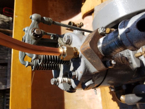 |
    
narrabay2
Senior Member
Username: narrabay2
Post Number: 114
Registered: 10-2019
| | Posted on Tuesday, July 21, 2020 - 07:41 pm: | 


|
bent and flared my first copper tube in like 20 years with so so results... I can do the updates a little more because it gets me into air conditioning for a few mins!
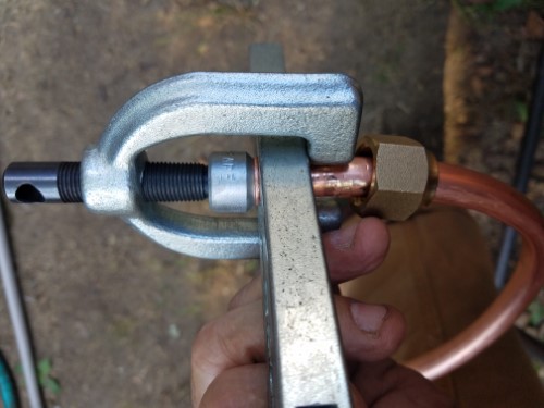
 |
    
narrabay2
Senior Member
Username: narrabay2
Post Number: 115
Registered: 10-2019
| | Posted on Wednesday, July 22, 2020 - 11:05 am: | 


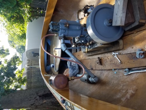
|
Mounted the SGP bracket to try and figure out a pump bracket which must be attached to the SGP. The recip pump inlet/check valve is in the way so ordered a 45 degree street ell to see if that may solve that clearance. When that gets here tomorrow, the coolant-tank loop should be done and can maybe even run up the YT with garden hose water running in the tank cooling coil.
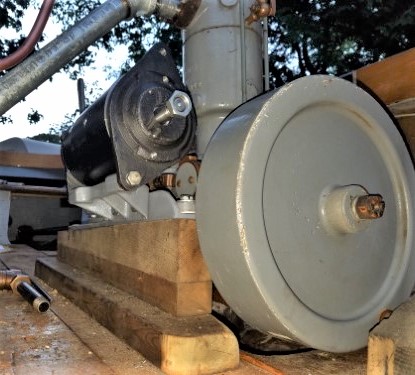
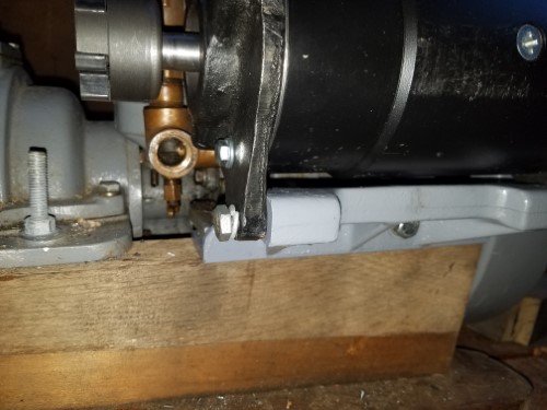 |
    
narrabay2
Senior Member
Username: narrabay2
Post Number: 116
Registered: 10-2019
| | Posted on Friday, July 24, 2020 - 09:11 pm: | 


|
The coolant loop is complete. may refine the copper runs later (go up to 1/2" on the inflow side so they match), but its complete right now. I used a compression fitting for the 3/8" line into the tank so I could stick the end of the tube above the bottom a but which should prevent any debris from being drawn in by the YT pump. I spotted teflon tape at the store that is not only 3.5 mills thick, but it happens to be kind of Palmer gray!
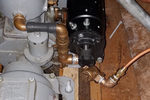
 |
    
ernie
Senior Member
Username: ernie
Post Number: 2603
Registered: 01-2002

| | Posted on Saturday, July 25, 2020 - 08:50 am: | 


|
Chris,
The pump drive on the back of the starter/generator looks real neat.
Don't forget to turn the water pump inlet check valve so it is straight up. It won't work vary good laying on its side.
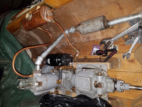
Can you put a street L at the head for the water out line? That way the high point will be the top of the heat exhcanger. In the pic it looks like the high point is the top of the loop in the line from the head to the exhanger. |
    
narrabay2
Senior Member
Username: narrabay2
Post Number: 119
Registered: 10-2019
| | Posted on Saturday, July 25, 2020 - 11:06 am: | 


|
Great minds think alike but for different reasons sometimes. I just now ordered a street ell / flare fitting for there. But my reason was that the "hoop" would be prone to damage. Anything or anyone hits that, and it kinks, maybe cracks, etc, not good. Didnt think that the tubing being higher than the tank would make much difference since the pump is a pos displacement pump and the coolant has no choice but to move. Went with the straight fitting on the head to minimize corners that something could get stuck in. Prob was being over cautious.
As to the check valve, it would be hard to reorient that vertically. It was installed dead horizontal when I got it and it pumped. Now, it is sloping down which will only help the flapper close during the pumps "compression stroke".
Its pretty close to a test run now anyway so we'll see how good everything flows through that tank...
I should add that besides a street elbow you mention, also ordered 1/2 fittings for that tank-to-pump line so it matches. supplyhouse.com has everything, ships fast, and great prices.
chris
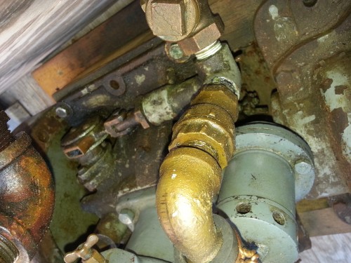 |
    
ernie
Senior Member
Username: ernie
Post Number: 2605
Registered: 01-2002

| | Posted on Saturday, July 25, 2020 - 02:02 pm: | 


|
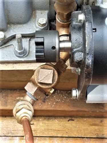
Chris the check valve only needs to be vertical related to the valve. Not the water flow. In the pic above the valve is in the vertical orientation operationally, not flow. If it gives you a problem the way it is just use a street L out of the pump and head the valve straight aft then it will be like its is above but away from the starter generator. |
    
narrabay2
Senior Member
Username: narrabay2
Post Number: 120
Registered: 10-2019
| | Posted on Saturday, July 25, 2020 - 02:23 pm: | 


|
Ahhh thanks Ernie. I can be pretty dumb about what I am looking at sometimes. I get it now. Will do... |
    
narrabay2
Senior Member
Username: narrabay2
Post Number: 121
Registered: 10-2019
| | Posted on Saturday, July 25, 2020 - 03:46 pm: | 


|
done. clears the lovejoy coupler by enough at all positions of the starter. now to fit a pump bracket to that SGP...
 |
    
narrabay2
Senior Member
Username: narrabay2
Post Number: 123
Registered: 10-2019
| | Posted on Sunday, July 26, 2020 - 06:50 pm: | 


|
Small progress, filled the coolant heat exchanger tank with fresh water, blew into the filler to force the water up to the cyl head outlet, and then turned the engine by hand. The pump packing nut needed a couple turns, and it does seem to pump fine. If I can find the woodruff key maybe I will put the belt on the starter, and start it up for a few seconds just for fun. (and see if a single belt slips. it didnt the last time).
Eventually going to find or make a 2 belt pulley. 5/8 shaft 3-1/2" od, 1/8" keyway, if anyone has a double pulley like that to sell...
Here's the exciting water pump video:
https://youtu.be/Hof0UZP3ywY |
    
bruce
Senior Member
Username: bruce
Post Number: 704
Registered: 07-2002
| | Posted on Monday, July 27, 2020 - 09:13 am: | 


|
WWW.Graingers.co will have the two belt sheave |
    
narrabay2
Senior Member
Username: narrabay2
Post Number: 125
Registered: 10-2019
| | Posted on Wednesday, July 29, 2020 - 08:12 pm: | 


|
Thanks Bruce, actually, found out that cub cadet starter shaft is around .670" inches, kinda odd size afaik. And the stub shaft only sticks out 3/4" before the threaded end. I may just weld two of the CC pulleys together and call it good.
Made the pump bracket today, I think it came out pretty good. So, getting there...
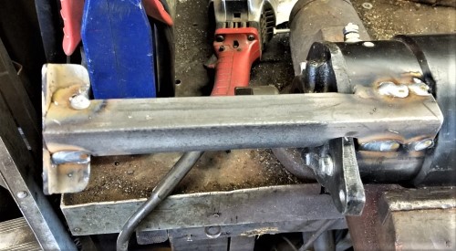
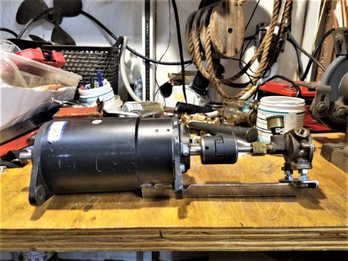 |
    
narrabay2
Senior Member
Username: narrabay2
Post Number: 126
Registered: 10-2019
| | Posted on Friday, July 31, 2020 - 10:58 pm: | 


|
Few more pics. Making mistakes but learning from them. For example, the hangar flange pieces I used to brace the copper tubes, are not copper, just copper plated. So, next winter I'll have to unsolder and redo the end of the coolant tank.
Also, turned the stub shaft down 2 thousandths too small at .623" . The lovejoy bore is a few thousandths oversize, So I ordered a new coupler half that is .500" and can bore that to match the shaft. Will use 2 set screws 90 degrees apart to fix it in place.
Still waiting for a few parts and some tooling for the cylinder head project, the postal service is running very slow.
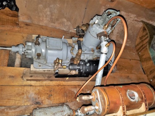
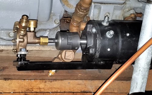
 |
    
narrabay2
Senior Member
Username: narrabay2
Post Number: 127
Registered: 10-2019
| | Posted on Sunday, August 02, 2020 - 04:28 pm: | 


|
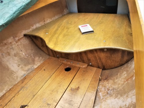
Front seat ready to bolt down, added some flotation under it using free dock foam I was given. will put some under the rear seat as well. dont want to lose the boat after all this effort!
also, got the new lovejoy coupler and bored that to match the shaft. It seems to be made of sintered metal which I didnt know what that was but it didnt seem like cast, and certainly wasnt steel, so after a google search came up with sintered iron as a likely material. someday i will make a coupler from steel.
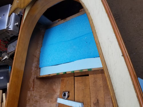
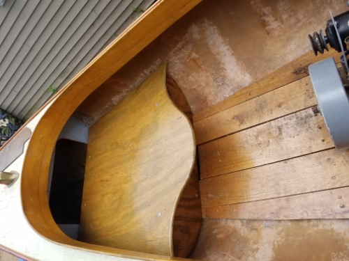
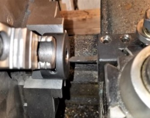 |
    
ned_l
Senior Member
Username: ned_l
Post Number: 220
Registered: 08-2012
| | Posted on Monday, August 03, 2020 - 11:23 pm: | 


|
Wow! great work! |
    
narrabay2
Senior Member
Username: narrabay2
Post Number: 128
Registered: 10-2019
| | Posted on Tuesday, August 04, 2020 - 03:25 pm: | 


|
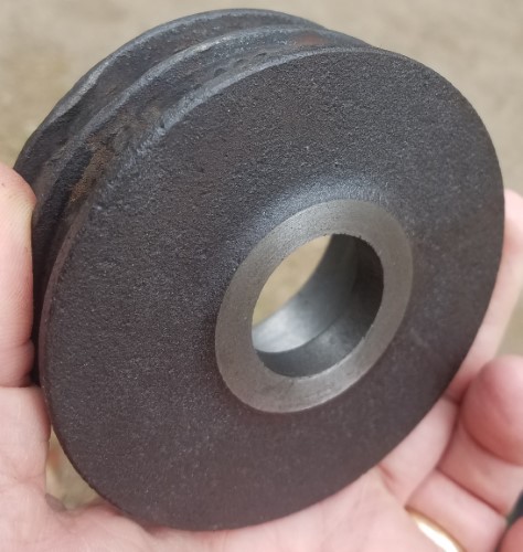
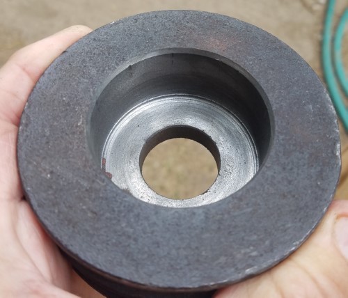
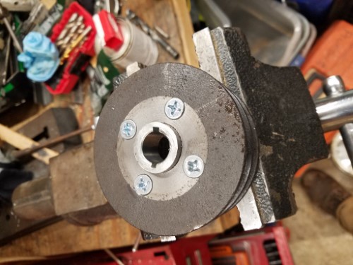
Thanks Ned.  Slow but steady progress, welded 2 sheaves together for temporary, but have a cast dual sheave I was just given. Turned it to prep for making a steel flange for it, see how that goes. Its a slightly larger diameter. Slow but steady progress, welded 2 sheaves together for temporary, but have a cast dual sheave I was just given. Turned it to prep for making a steel flange for it, see how that goes. Its a slightly larger diameter.
Also modified the center plank so it can be lifted out easily for bilge access.
Exciting short video clip of a quick starter test:
https://youtu.be/nsH_WQYdHnU
 |
    
narrabay2
Senior Member
Username: narrabay2
Post Number: 129
Registered: 10-2019
| | Posted on Sunday, August 09, 2020 - 05:21 pm: | 


|
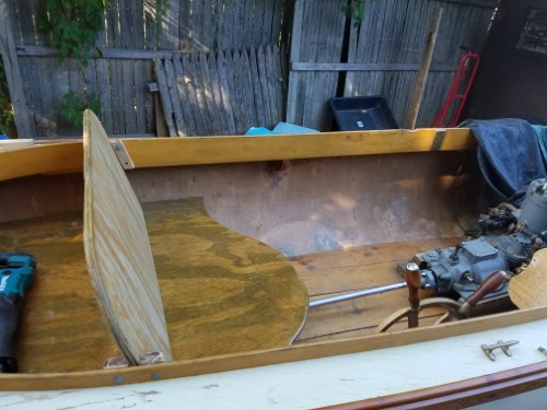
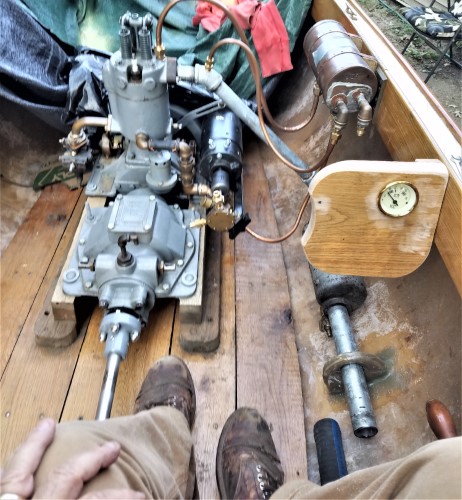
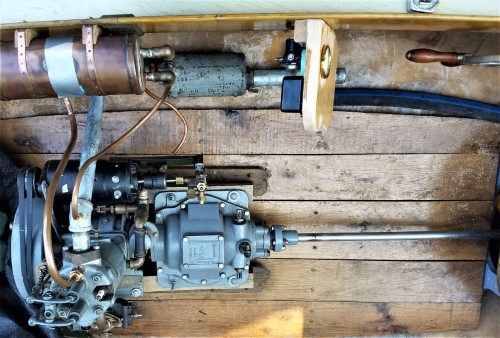
Some progress, installed a muffler hard point to support that. Need to touch it up but its strong. Made a quick slide-in seat back, not all that pretty so will make some more decorative woodwork after the season. The mounts are attrocious but will do for now. Used some leftover oak to dummy up a little switch panel with a retro marine voltmeter keep an eye on the battery. Dont want it to go flat when I'm towing someone in or anything like that.  Turned out to be a convenient place to mount the cub cadet regulator and solenoid that go with the Delco starter-generator. Ordered an old brass starter button from ebay too. Turned out to be a convenient place to mount the cub cadet regulator and solenoid that go with the Delco starter-generator. Ordered an old brass starter button from ebay too.
The pump is pretty much all set, just need some longer bolts and that are stainless. Need to add a battery tray on the left side somewhere under the seat, to balance the weight at least somewhat, and install the oar locks up front. Also still working out where to put the raw water strainer and the buzz coil. If much more time goes by they may end up duct taped to the exhaust pipe or something. haha
 |
    
narrabay2
Senior Member
Username: narrabay2
Post Number: 130
Registered: 10-2019
| | Posted on Monday, August 10, 2020 - 05:24 pm: | 


|
small update. I may just make a wooden battery/coil/regulator everything box - keep everything dry. even have a spare quick change buzz coil in it.
I was hoping to put the battery on the other side to balance my own weight but its too clean to put it all right there next to the muffler. maybe the gas tank, anchor and everything else can be put on port side somehow.
all these little things that have to be decided! |
    
narrabay2
Senior Member
Username: narrabay2
Post Number: 131
Registered: 10-2019
| | Posted on Friday, August 14, 2020 - 09:43 pm: | 


|
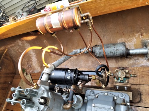
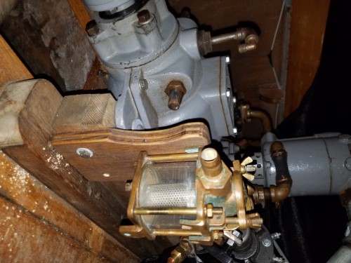
OK got the machined hub fitted to the cast double pulley, and the plumbing is all in place except for thh raw water supply. I put a slight double flare on the copper line where the rubber hose connects. (since the pump moves when changing the belt etc, it seemed a rubber section was in order)
 |
    
narrabay2
Senior Member
Username: narrabay2
Post Number: 132
Registered: 10-2019
| | Posted on Wednesday, August 19, 2020 - 01:06 pm: | 


|
Small update: Starter test. Larger pulley turns the YT fine. Interestingly, heavy jumper cables didnt provide enough current. But when I made up some proper battery cables and a starter solenoid, works fine. I forgot to shut the drip oiler last night and now its all in the crankcase. MIGHT test run the engine today or else soon. Ernie put the top end together with me so at least I know that's a-ok. One step at a time! 
https://youtu.be/8pmSeyxHgiE |
    
narrabay2
Senior Member
Username: narrabay2
Post Number: 133
Registered: 10-2019
| | Posted on Wednesday, August 19, 2020 - 03:03 pm: | 


|
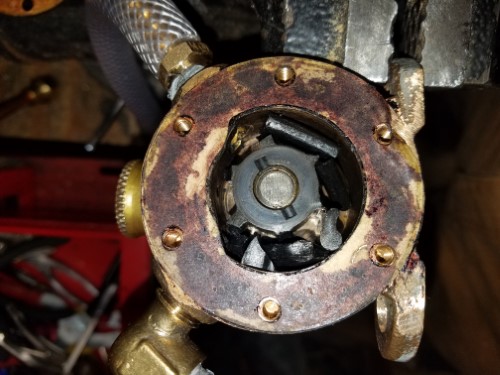
OK bigger update I decided to just run it. Oiled everything up, put water in a raw water tank, and away we go as Jackie Gleason would say... couple observations, its very quiet. The little tiny Jabsco moves a LOT of water, all of which goes into the exhaust pipe. May put a valve on its inlet. I had to play with the choke to keep it running as havent set the carb yet. The Header tank got slightly warm as did the engine head. One push rod was rotating nicely, the other wasnt, not sure about that or it its even an issue with everything lubricated anyway.
So next thing is to get the choke and throttle cables installed and then adjust the carb.
I ran last years fuel mix from the Gray. I little extra top end lube cant hurt I dont think. Also, have to make a better observation, but didnt seem to have that big issue of oil flying out of the breather. When Ernie and I put the top end on we ran it briefly and he said the breather was popping away as it should. So maybe before it was just blow-by and the new cylinder sleeve and rings has helped. Need to double check that no oil's coming out when I can let go of the carburetter controls.
Oh, the first Jabsco impeller crumbled. Not sure if it was china junk, or NOS that got dry. Had another and it worked fine (so far) I'll have to see if Jabsco still sells those oem.
Here's a Video of the YT-1 running
https://youtu.be/mCrL40C4eR4
 |
    
ned_l
Senior Member
Username: ned_l
Post Number: 222
Registered: 08-2012
| | Posted on Thursday, August 20, 2020 - 03:21 pm: | 


|
Congratulations! it looks and sounds great. |
    
narrabay2
Senior Member
Username: narrabay2
Post Number: 134
Registered: 10-2019
| | Posted on Thursday, August 27, 2020 - 11:50 am: | 


|
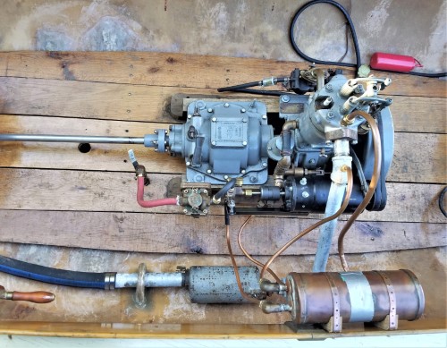
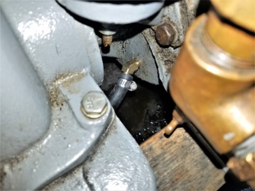
A little more progress, after a car repair project and a cupola rebuild on our house. New raw water thru hull is in, added an oil overflow drain fitting and a shut off behind the trans where I can reach it. Found a 1/8" NPT to 3/8" hose barb 45 fitting - perfect... That allows the excess oil from the drip oiler to be drained off. I left the drip oiler on twice already so its important. Updated the pump bolts to stainless, bought two push pull choke cables for throttle and choke to be at oper station however they are sloppy and still trying to figure out how to control throttle and choke reliably. Also made an electrical box that fits battery, coil, regulator, and solenoid. Also not sure about that approach. Looked into a heavy 7-pin trailer connector to have a quick disconnect for that to take it out of the boat when not in use. Just not sure. The starter and pump works great with the larger pulley. Hopefully shouldnt be long now.
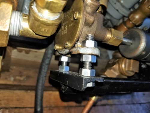 |
    
narrabay2
Senior Member
Username: narrabay2
Post Number: 135
Registered: 10-2019
| | Posted on Sunday, August 30, 2020 - 08:38 pm: | 


|
back to my little panel idea.
key switch, choke, throttle,
running lights, interior lights,
bilge pump (off/on/auto),
and a battery volts meter.
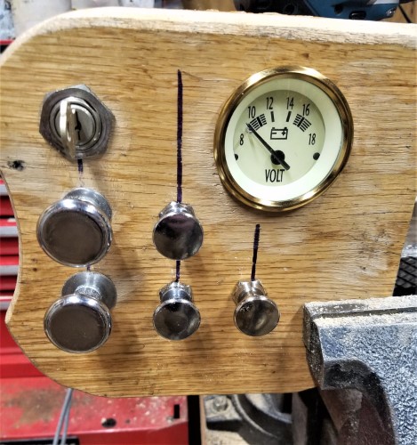 |
    
narrabay2
Senior Member
Username: narrabay2
Post Number: 136
Registered: 10-2019
| | Posted on Tuesday, September 01, 2020 - 05:00 pm: | 


|
OK well it runs but a few issues getting sorted out. Seemed to run too warm so I connected the cooling to a bucket to check pump flow. It is pumping but I dont know what good flow looks like but I think its ok. The cyl head is around 170f on the outside. Breather is losing oil still, crank case oil level is right, no idea. The tank isnt gravity feeding, need to look at that quick connect. Carb adjustments went well and it idles well. Choke and Throttle and Key Start works well. Still have to do wiring, battery install, regulator, and that stuff. Havent really proved the Jabsco, hooking that back up soon.
Probably ran it a good hour though, the longest to date.
Anyway here is a video mashup of the engine running and a few tests.
https://youtu.be/RC4MFGhQN64 |
    
narrabay2
Senior Member
Username: narrabay2
Post Number: 137
Registered: 10-2019
| | Posted on Tuesday, September 01, 2020 - 07:41 pm: | 


|
OK when the jabsco was hooked up, there was a strong vibration. I finally figured out a test (Im slow) to isolate the sound by disconnecting the vee belts and run the SGP and turn the key. Sure enough, the pump really vibrates. Wonder if this is normal or what. The impeller looks ok. I suppose the shaft could be checked for runout. The vibration is enough that I dont want to run it without fixing that. I wonder if that angle iron bracket is not stiff enough and a weight attached may help? Its a very small pump but moves a lot of water. When I make the starter end plate with built in pump I can always make that smaller if I can source a small impeller. Here's a video clip:
https://youtu.be/GU_F7hZ5WRI |
    
narrabay2
Senior Member
Username: narrabay2
Post Number: 138
Registered: 10-2019
| | Posted on Friday, September 04, 2020 - 12:21 am: | 


|
Been puzzling over that Jabsco pump whine. It also moves too much water which takes from that 2hp the YT produces. I am thinking and thinking, and even though a pump housing end plate for the starter is coming eventually, it would be nice to get this settled and run the boat.
So, its a rubber vane impeller pump. It vibrates and moves too much water. That could be from the lack of mass it's bolted to. Nonetheless, if the impeller spun in a perfectly round cavity, it couldnt really vibrate (or move water). So the ONLY feature (we learned that term in machinist school!) that can cause this is the "cam" which is a bump out within the pump cavity between the inlet and outlet ports. It happens to be attached with a screw. I may try to make a new one that is much less aggressive (thinner). See pic a few posts above. May give that a try. If it makes the pump more "tame" may just bring this all together. |
    
narrabay2
Senior Member
Username: narrabay2
Post Number: 139
Registered: 10-2019
| | Posted on Friday, September 04, 2020 - 08:33 pm: | 


|
UPDATE the vibration is not the pump itself, it seems to be the coupling or possibly the alignment of it. Although the coupling gap was even to the eye and these are designed to handle some misalignment. So I made a solid coupling, and interestingly I had to bend the angle iron bracket over a bit to get the pump bolts to line up.
Unfortunately I dont have the set screws to test it in place tonight.
VIDEO of pump running smoothly on a drill motor:
https://youtu.be/u09wIcXOIzE
Coupling:
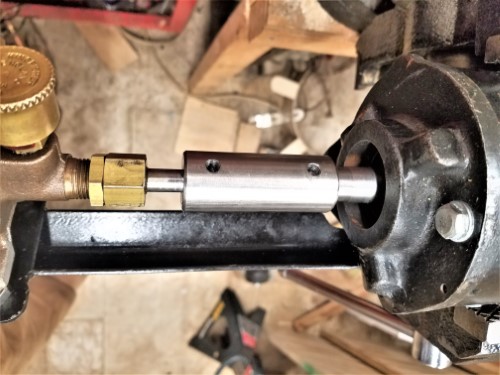 |
    
narrabay2
Senior Member
Username: narrabay2
Post Number: 140
Registered: 10-2019
| | Posted on Sunday, September 06, 2020 - 06:29 pm: | 


|
Well that didnt work. The pump was moving over .040". The stub shaft has .001" runout at the end, but the adapter coupling I made on the lathe has about .020" runout at the pump end so the bore (done with drills from a chuck in the tailstock) must not be straight. And the rest is just angular amplification and maybe a bit of runout on the pump shaft itself. The Tee bracket was moving with the pump confirming my suspicions that it wasnt really beefy enough.
Soooo... out came the sawzall. Pics show the rest. I welded a heavy piece of angle to the stump of the old tee bracket and to the thick starter housing. Only have a stick welder and out of practice so not the prettiest welds. THEN discovered it was too short - didnt realize the cast iron starter bracket was there. Out comes the sawzall and welder again and added an inch to it. Now it works.
If I had to do it again, I'd flip it so the pump is on top so as to be seen (its bronze!). But when the 2" pulley comes Tuesday, and a 19" 3L vee belt, this should HOPEFULLY solve all the pump issues once and for all. as a bonus, it will run at half the speed, which will still probably be still more than needed. But thats half the parasitic loss, half the impeller wear, half the opportunity to vibrate etc. So this should move things in the right direction.
This is truly fun to be doing (and re-doing)! 
Yesterday was our anniversary and my wife gave me a nice card that ends with "I can't wait to ride in the boat!"
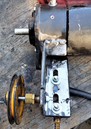
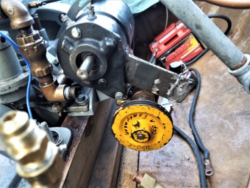 |
    
narrabay2
Senior Member
Username: narrabay2
Post Number: 141
Registered: 10-2019
| | Posted on Tuesday, September 08, 2020 - 06:40 pm: | 


|
Ok I was able to trim the bracket and flip the pump to the top, progress! Almost ready for a 2-pump test run... also found a spare carb with flame arrestor in good shape cheap. I think its the same zenith. It looks to have a brass suction tube to the belly of the throat which I think makes it the marine version.
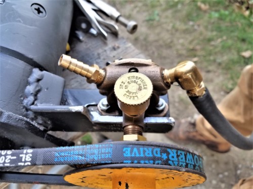
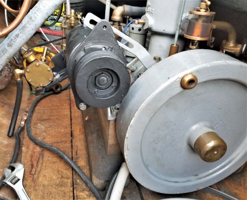
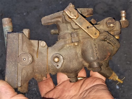 |
    
narrabay2
Senior Member
Username: narrabay2
Post Number: 142
Registered: 10-2019
| | Posted on Tuesday, September 08, 2020 - 08:36 pm: | 


|
And... another thrilling video... this time belt driven pump test. Seems like it will be A-ok this way.
https://youtu.be/i1KtbyQm6ao |
    
narrabay2
Senior Member
Username: narrabay2
Post Number: 143
Registered: 10-2019
| | Posted on Tuesday, September 15, 2020 - 12:42 pm: | 


|
Ran the YT for a solid hour today. Around 450-500 rpm. The head got to 217 on the outside and the header tank coolant was over 140 after a while. This is with no load. The raw water loop of 40" 1/2" copper is surprisingly not enough. So I may add a heat exchanger below the header tank/exchanger, or run a keel loop. Whichever is easier.
That being said, I had found a rule of thumb for 12 square inches of keel cooling per HP, in my case that means 24 sq inches at FULL power. My 40 inches of 1/2" copper pipe has 63 square inches of surface area, which is 2.5 times the needed area. More than double. And the raw water is from the garden hose running into a bucket (not recycled) then out the exhaust so its like 50f degrees... the sea water around here now is around 70f.
In this case, the cold water is inside the copper pipe and the hot engine coolant flows around it from one end of the tank to the other. The coolant in the tank runs 145f max at idle, no idea what putting a load on it would max it out at. So for some reason that 40" of cold water piping is not removing enough heat from the engine coolant.
Also the breather is still tossing black oil droplets all over the place so I may find a way to capture that to a catch tank. The oil level was still full after the run (the drip oiler adds oil to the engine) so its not apparently losing much oil.
But an hour is good, it idles pretty well and I got that down to about 425 RPM reliably.
The tank was high up on the front deck and still not siphoning (had to squeeze the primer bulb everv few mins). I changed the quick disconnect to a barb which seemed to help but not completely. There is a small fuel filter plus the primer bulb check valves maybe thats holding it back? Hope I dont need to add a fuel pump! (Ernie had added one on the gray). Not sure where one could be added unless there is a very low pressure electric fuel pump made... hate to remove that lawn mower fuel filter... I see others gravity feed with head of a head than this and I cant run the tank up on the bow anyway so another issue to solve but this one cant be that hard!
This is a few clips from the 1 hour run... enjoy! BTW I make these videos here unlisted, but will make a good one sometime and list it so others can find it. Not many YT-1 running videos out there, so I think it would be good to share once this is all sorted out.
https://youtu.be/-iRi7G7TtUA |
    
narrabay2
Senior Member
Username: narrabay2
Post Number: 144
Registered: 10-2019
| | Posted on Tuesday, September 15, 2020 - 08:04 pm: | 


|
OK update - engine cooling. Bought a long marine transmission cooler (red thing in the picture) at the used shop. Plumbed it in quick job with rubber hosing and ran it. The coolant goes to the tank first, then through the cooler. The tank never got above 100 maybe even less. Cyl head was still 177f on the outside which is 40f less than it was yesterday without the cooler added (this after 30 mins running). I also checked for air by removing the top fitting on the head, and the coolant was at the very top of the flare fitting. So just filling and running it is enough to push out any air apparently.
I think the cooling is resolved (once I mount this cooler out of the way under the gunwale and plum it in more neatly).
That breather is still throwing an oil shower, so thats next on the agenda. Ernie may loan me an old style one and we'll see and I have to take this one apart make sure its clean and in shape and re-adjust it.
Worst case I will make some kind of a cover with a filter for the breather to catch the oil into a catch can.
Now to get after the entire bilge and floor and engine etc with dawn and simple green!
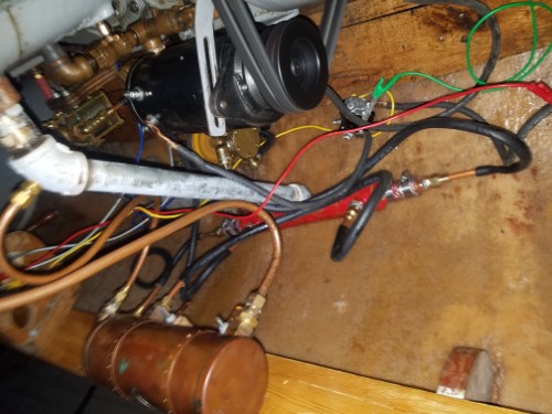
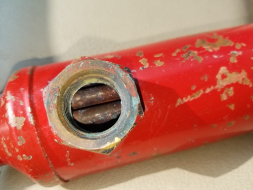
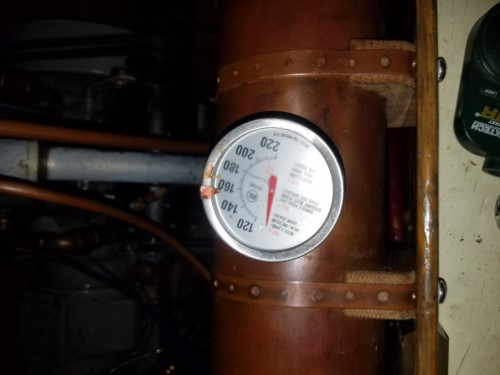 |
    
narrabay2
Senior Member
Username: narrabay2
Post Number: 145
Registered: 10-2019
| | Posted on Sunday, September 27, 2020 - 12:34 am: | 


|
Found a way to mount the cooler... also bought some 3/8" red goodyear (USA Made) air hose to use for water lines. Still have copper from the head to the tank but I may add a rubber section after seeing the motor moving more than I thought despite being bolted down solid to the ribs. Dont want that line to suffer metal fatigue when at sea. A little more plumbing and the wiring, and can take it for a test ride I think. Trailer could use another center roller or two but thats not critical.
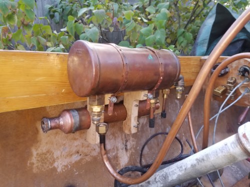
Starting to shape up...
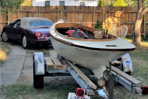
Turned the threads off some 3/4 brass fittings with 3/8 female pipe thread openings, and soldered them into the ends of the cooler.
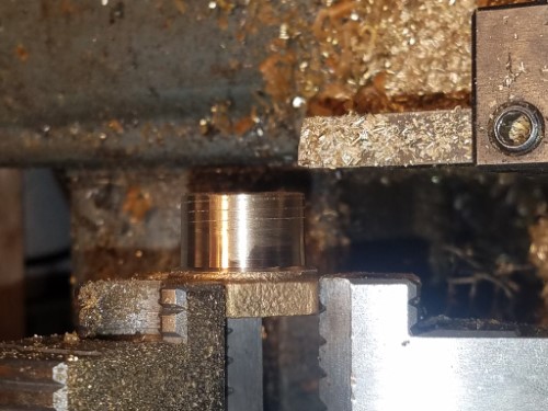 |
    
narrabay2
Senior Member
Username: narrabay2
Post Number: 146
Registered: 10-2019
| | Posted on Wednesday, September 30, 2020 - 06:57 pm: | 


|
Well finally got some yard chores out of the way and back to the Fantail. Today ran the fuel line and battery cables through the ribs. Big AGM battery is up front. Now just have to run the rest of the wiring (starter, ignition, running lights, regulator, etc).
Also, my friend who did the machining on the dispro was previously operated his commercial fishing vessel offshore and made a comment that the oak will eventually turn black no matter how much urethane is on it. He's right. he also mentioned that the old timers liked knotty pine for the flooring because you can keep it looking good and the knots provide wear resistance. Interesting! In this case, turning black or not I like the strength of the oak.
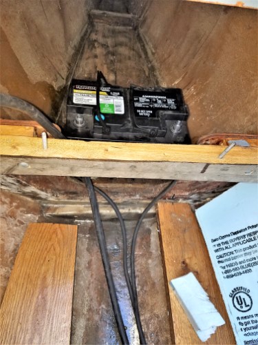
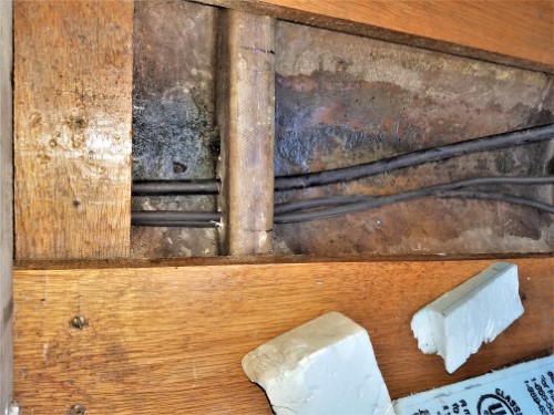
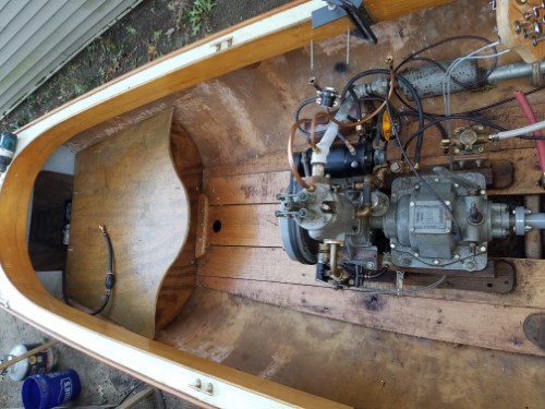 |
    
chris_spring
Senior Member
Username: chris_spring
Post Number: 74
Registered: 02-2019
| | Posted on Thursday, October 01, 2020 - 04:44 pm: | 


|
I used clear pine for the Gidley. Light. Cheap. Wearing well. I used knotty pine in a hydroplane I restored. I was looking for light and cheap. |
    
narrabay2
Senior Member
Username: narrabay2
Post Number: 147
Registered: 10-2019
| | Posted on Friday, October 02, 2020 - 05:41 pm: | 


|
Thanks Chris. That sounds like a good option for the Dory which the Gray is going into... |
    
narrabay2
Senior Member
Username: narrabay2
Post Number: 148
Registered: 10-2019
| | Posted on Sunday, October 11, 2020 - 10:42 am: | 


|
Got the battery in the nose hooked up and cables thru the bilge, to the solenoid and starter, so the heavy 12v is done. Going to try to run with just the cooler and not use the loop in the tank - it may be redundant. Getting closer to a Fall test drive.
If/when everything works reliably, will reengineer the plumbing and electrical for neatness (hide as much as possible).
(Then get back on finishing the spare cylinder head) |
    
narrabay2
Senior Member
Username: narrabay2
Post Number: 149
Registered: 10-2019
| | Posted on Sunday, November 01, 2020 - 12:35 pm: | 


|
Other things got in the way of progress, but it's down to a few wires (have all the tinned marine wire and tinned connectors) for at least a test run. Might get a few more warm days to give it a shot for sea trials and generate the fix-list.
Prop shaft has a little (.035") runout at the stuffing box. I did not check that so no idea if it came that way but at these rpm's its ok for now.
Sometime, I should get a long, heavy Channel Iron with vee blocks bolted on to check and adjust these issues.
If the heat exchanger alone is sufficient, then there will be some opportunity to clean things up a lot between the YT and that side of the boat which right now has water lines, wires, and the exhaust. How much can be hidden is another question.
Finally, when this is working reliably, time to finish that cylinder head and get that tested and dialed in. That will be a nice feeling to have fresh thick steel cyl head. And I have enough 5" round to make one more after that. |
    
narrabay2
Senior Member
Username: narrabay2
Post Number: 150
Registered: 10-2019
| | Posted on Tuesday, November 10, 2020 - 04:50 pm: | 


|
Well, a few more items taken care of. Most will be redone more beautifully but they are OK for now. Rear rudder post access was a neat bronze deck plate with a cleat on it that somehow stopped in the right orientation. But my fat hands simply couldnt work thru it, so increased the hole and what u see is a temporary plywood cover. But I ran the router around it and used bronze screws into the stiffener underneath. Functional until something better. Really was stuck on where to put the Ford Model T the coil. So I just now made a wooden box and cover and it can go on the floor near the water strainer. Once it dries will get stain and varnish. And I installed oar locks, also quick job that will be done much nicer later with pads made with the scroll saw. Got the running lights hooked up and even the volt meter light in the circuit. Even without the regulator hooked up yet, that giant AGM battery in the nose will last far longer than needed Im sure.


 |
    
narrabay2
Senior Member
Username: narrabay2
Post Number: 151
Registered: 10-2019
| | Posted on Tuesday, November 10, 2020 - 04:52 pm: | 


|
rmv dbl post |
    
narrabay2
Senior Member
Username: narrabay2
Post Number: 152
Registered: 10-2019
| | Posted on Monday, November 30, 2020 - 01:49 am: | 


|
Sea Trials... day was too nice, so I threw everything into the boat in a hurry and headed down to the ramp. It seems a little overpropped but thats good. Ran very well, no surprises or failures of any kind as yet.
https://youtu.be/1qMCht2KXkw |
    
ernie
Senior Member
Username: ernie
Post Number: 2614
Registered: 01-2002

| | Posted on Monday, November 30, 2020 - 07:55 am: | 


|
Looks like fun
Ernie |
    
chris_spring
Senior Member
Username: chris_spring
Post Number: 82
Registered: 02-2019
| | Posted on Monday, November 30, 2020 - 01:09 pm: | 


|
It moves right along. Well done!
Cheers! |
    
narrabay2
Senior Member
Username: narrabay2
Post Number: 153
Registered: 10-2019
| | Posted on Monday, November 30, 2020 - 02:25 pm: | 


|
Thanks guys. Yes Chris it does seem a bit faster than then the Gray 3hp if I am remembering correctly. Certainly more than fast enough anyway. Half speed seems just right and also min speed is very leisurely and peaceful.
I put together a list from the sea trials. Some more important than others and many are to refine the appearance of things like the little temporary instr panel, oar mounts, seat back, and deck which will vastly improve the looks I think. As to the engine, the cheapo throttle cable screams for an update.
The boat lists to the right more than I thought it would when sitting still. The starter is heavy but very close to the engine. I really want to keep the left walkway clear so the coil box has to stay to the right, and the header tank is really not all that heavy. Up in the nose is a full size AGM car battery. I can relocate that to the left under the front seat and it would be a hassle but I could move the heat exchanger somewhere and the copper header tank up on the bow or something.
These engines sip fuel. I am still working off the original oil-mixed 3 gals I bought last year! Still about half left!
Maybe I can make a smaller and old-school 2 gal tank and put that on the left side of the front seat. It kind of was there anyway though. I think 2 gals would be more than enough.
but the main thing is that I managed to built it including total teardown cleaning of sludge, inspection, etc of the YT including cyl sleeve, rings, (get to know the engine!) and have it actually all work correctly. Made the companion flange and prop shaft. The shaft btw has runout of .035 at the stuffing box, I spoke with a shaft shop and he said even new material they often have to true up. Still working on a way to do that without paying $200+ for the service. Saw a cool video where brief spot heat is used to contract the metal on the high parts, pulling it straight.
https://youtu.be/ub7JSn81BKo
retorque head and exhaust bolts. head gasket sealer stop seepage (?)
check and then change crankcase oil
stronger throttle return spring
better (aircraft vernier?) throttle cable
true up prop shaft (has .035" runout)
wrap exhaust hot section
lock washers on cooler mount nuts that came or were loose
shackle and new short galv chain on anchor
flush salt water out of exhaust etc
spark plug socket in boat tools
streamline water hoses and copper lines finish copper wire clamps
make new wood instrument panel, with enclosed back
make all-new solid wood seat back, lower profile, nicer
trans cover gasket sealed
install voltage regulator (LOW priority)
make a hold down for coil box
whip dock line ends w twine
cover under rear seat to hide foam etc
interior light or shorty wooden mast w anchor light
Finish that new cylinder head
Move battery to left side if possible to correct list
Better old looking storage wood crate, wicker etc
Make decorative oar lock socket mount pads (type of wood?)
sand and seal cracks/delamination in deck, apply deck cloth
make oar stowage racks inside starboard side if possible
find furuno radar tower and radar unit (joking!)
trailer - rope covered rear vert guides equal widest beam of hull
trailer - another roller will be 2nd one back
trailer - vee-bunk(s) to cradle and center the hull when hauling
trailer - replace rear lights add side markers
I should add that Ernie has been a big help from first selling me the YT, all the advice and parts etc, and ever since so thank u Ernie.
|
    
narrabay2
Senior Member
Username: narrabay2
Post Number: 154
Registered: 10-2019
| | Posted on Friday, March 05, 2021 - 04:47 pm: | 


|
Cleaned and oiled the Cuno Timer contact roller, and presto... winter test startup
https://youtu.be/TEJS5SAStA0 |
    
narrabay2
Senior Member
Username: narrabay2
Post Number: 156
Registered: 10-2019
| | Posted on Tuesday, March 23, 2021 - 08:29 pm: | 


|
Today was a struggle to control the oil blasting out of the breather unit. It's a very solid and cool unit that Palmer designed. Took it off and apart, and cleaned it although it was already pretty clean. There is an adjustment that is very hard to get to on my YT due to the transmission, until you get the knack.
But interestingly, upon close inspection, it appears there is also a top adjustment to stop the piston at the top of its travel. Thats the same threaded rod that the top nut goes on to hold the cap on. There's a stop nut on it and it can be moved up and down by turning it. But as short as it was it couldnt be turned any lower.
I looked at the check valve piston cup and it has four horizontal flutes that expose when it moves up. So at its top position, the engine expels crankcase gasses out the breather. When the engine piston goes up creating suction in the crankcase, this breather piston gets pulled down and the flutes are against a bore (closed).
In my case, it was going to where the flutes were exposed (open to flow), and then it was going farther and the bottom skirt was exposed past the bore. I am pretty sure (although who knows) that Palmer designers did not intend for the flutes to be supplemented by moving the piston even further and having it open all the way around the bottom too.
The threaded rod stud was too short (and looked cut off at the top), so I put a longer one in and set the piston to stop when the flutes are open, but not further.
Put it back on and applied Dick Day's documented adjustment procedure. The first time it still got wet and dripped from the vent holes a little, but after adjusting it again, it seems to have stopped. Certainly its a lot less.
Before, there was oil all over everything after running the engine it just spattered out of the breather vent holes like crazy and I even tied a cloth loosely around it to soak it up.
Now hopefully things will stay cleaner. The only other oil that gets loose is a few runs after lubing the various oil points, easy to wipe up with a rag.
Engine started instantly, coolant circulating well, fresh water through the heat exchanger into the exhaust and it ran very very steady at 400 rpm. I did get it down to about 370 RPM but that's about the lowest she will idle (checked using little digital tachometer).
First pic shows the threaded rod that I think may have been a little too short. Second pic is the breather check valve piston moving past the bore.
Anyway its popping away normally and *seems* to be keeping the oil in. We'll see soon on a long boat ride! 

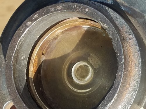 |
    
narrabay2
Senior Member
Username: narrabay2
Post Number: 157
Registered: 10-2019
| | Posted on Friday, March 26, 2021 - 07:58 pm: | 


|
OK the breather is resolved it would seem! Next is idle. I could never get a reliable idle under about 450. Was determined to get that lower, after making very small adjustments to idle set screw, timing, and idle mixture, got a steady 250RPM. It certainly isnt something you can just close the throttle and expect it to stay running, but nudging it down (and back up when power is needed) works.
Here's the exciting video of a Palmer YT-1 running at 250 rpm. This is 5 mins out of a total 20 minutes at that speed. Motor stayed nice and clean too 
The last minute of this video is another angle to watch...
https://youtu.be/1TwjDD8fbL8 |
    
dick_briggs
Advanced Member
Username: dick_briggs
Post Number: 43
Registered: 02-2015
| | Posted on Saturday, March 27, 2021 - 12:11 pm: | 


|
Looks and sounds like you have it very well dialed in - now we need another video of it cruising... |
    
narrabay2
Senior Member
Username: narrabay2
Post Number: 158
Registered: 10-2019
| | Posted on Saturday, March 27, 2021 - 06:55 pm: | 


|
thank you dick. looking around for an aerial drone operator to follow the fantail through the harbor as long as its not too terribly expensive... looking now but wont do it until there's leaves on the trees. of course there's always the usual phone camera stuff for now. weathers real nice so if that hold should be in the harbor again soon |
    
ernie
Senior Member
Username: ernie
Post Number: 2633
Registered: 01-2002

| | Posted on Thursday, April 01, 2021 - 06:32 pm: | 


|
Chris,
I bet you are glad to have that handled.
Nice work
Ernie |
    
narrabay2
Senior Member
Username: narrabay2
Post Number: 159
Registered: 10-2019
| | Posted on Monday, April 05, 2021 - 06:14 pm: | 


|
Thanks Ern, looking to take ur advice and streamline the cooling plumbing a bit better (although still cant visualize the best way yet), and hoping to maybe put the little switch panel below the gunwale and parallel to it. It's very handy. Someday maybe swap for brass pulls on the switches as well.
Stripped that yellow Jabsco pulley which came from a Farymann diesel. That yellow paint came off hard! Multiple rounds of aircraft paint remover and power wire brushing. But now it will match.
Started up instantly today and idled down to 220rpm easily! You're right once you get that zenith carb set, it stays right.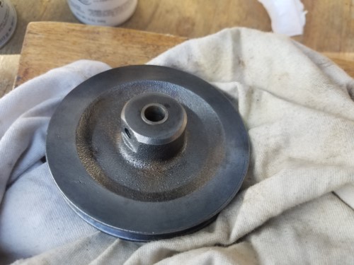 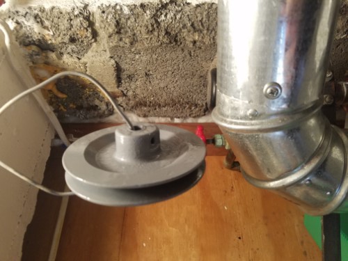 |
    
narrabay2
Senior Member
Username: narrabay2
Post Number: 160
Registered: 10-2019
| | Posted on Friday, April 09, 2021 - 10:48 pm: | 


|
Well could not easily see the drips in the drip oiler sight glass, so I made a bigger one. Just need to cut gaskets and then cut the screws off to the right length. 9/16" - 18 threads on the top and 1/4 NPT on the bottom. Used taps for that. Could be more ornate and all that but this was a first version and wanted to keep it simple.
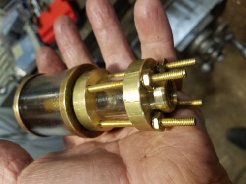
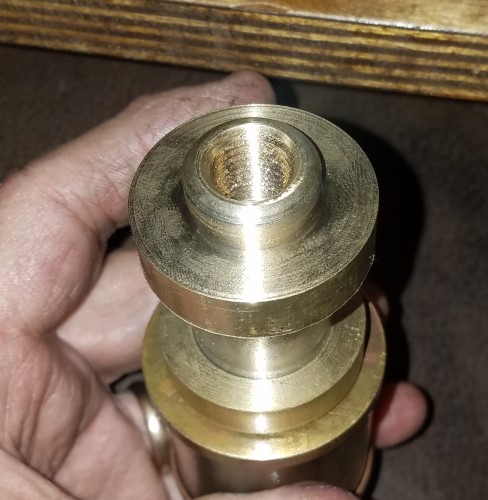
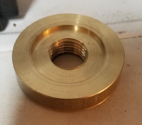 |
    
narrabay2
Senior Member
Username: narrabay2
Post Number: 161
Registered: 10-2019
| | Posted on Saturday, April 10, 2021 - 03:04 pm: | 


|
Going to raise it an anch or so, but it looks functional. I added more holes to the hollow center tube (from 1 to 4) and a felt ring to prevent clogging of the needle. May make a new bottom piece with threaded holes as I'm not crazy about the bottom nuts showing. Anyway, easier to see the drips.
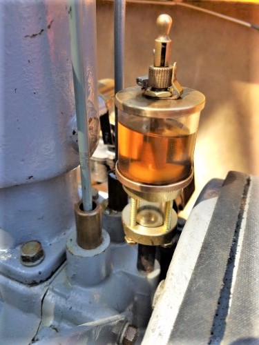 |
    
narrabay2
Senior Member
Username: narrabay2
Post Number: 162
Registered: 10-2019
| | Posted on Saturday, April 10, 2021 - 06:00 pm: | 


|
Ok well with the YT running, the drips would run along the "ceiling" or else get tossed against the glass. I added an extension to the nipple with brass tubing and silver solder which looks to have finally gotten it going. Also, while it was dripping initially, I had trouble and though the felt may have swelled or something so that's why that's out. I do want a filter material in there though but not urgent.
and for those who can handle the excitement of these videos. here it is in action.  enjoy! enjoy!
https://youtu.be/ePeZg3MUhQo
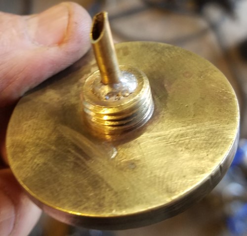 |
    
narrabay2
Senior Member
Username: narrabay2
Post Number: 164
Registered: 10-2019
| | Posted on Thursday, April 15, 2021 - 07:18 pm: | 


|
Straightened the prop shaft from .050" runout to about 2 or 3 thousandths.
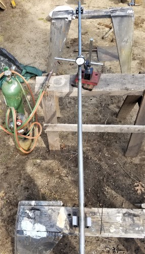
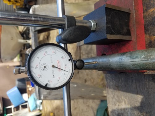 |
    
narrabay2
Senior Member
Username: narrabay2
Post Number: 168
Registered: 10-2019
| | Posted on Sunday, April 25, 2021 - 10:43 pm: | 


|
Reconfigured the plumbing to minimize the clutter! better little expansion tank coming, this one is temporary. Ran it up today, the Jabsco didnt catch prime for some reason until I flooded it. This is unusual so I will check the impeller. Next up - the electric and instrument arrangement... also to be cleaner and neater and minimized.
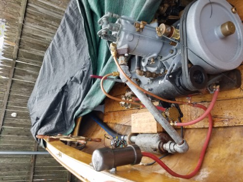
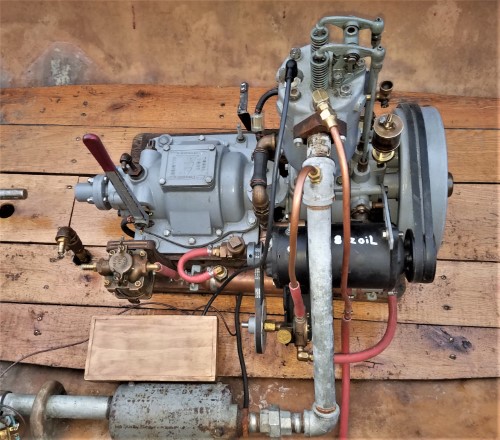
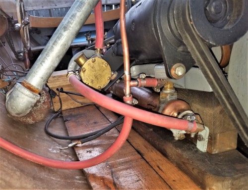 |
    
ernie
Senior Member
Username: ernie
Post Number: 2635
Registered: 01-2002

| | Posted on Monday, April 26, 2021 - 09:58 am: | 


|
Chris,
Looking good.
Please start a new thread on this. It is getting pretty long. Lots of posts and lots of pics.
Just Fantail Launch Updated Volume 2 or something like that.
Thanks
Ernie |
    
queeniebee
Member
Username: queeniebee
Post Number: 4
Registered: 05-2021
| | Posted on Saturday, October 16, 2021 - 02:30 pm: | 


|
Dear Chris,
Just came upon your YT-1 posts, wow what a lot of great information. Recently I refitted my Chesapeake Crab Skiff with a 1930 YT-1. The engine is in remarkable condition and only involved minor installation changes.
What size prop are you using?
I am using a CHRIS CRAFT PROPELLER THREE BLADE #7907 RIGHT HAND 11.5 X 9 (1047)
And it seems too much prop for the application.
Notes:
Skiff: flat bottom, length 16 foot, beam 64 inches with white oak frames and juniper side and bottom planking weight unknown.
Engine: Palmer circa 1930, four cycle, 2 horse power at 800 rpm. Palmer sales manual specs engine 98 pounds, diameter flywheel 12 inches, diameter propeller 10 inches. The engine turns counter clockwise.
Reverse Gear: Gies Gear Special #1 circa 1908
Propeller shaft: 7/8� diameter
Clear skies, fair seas
Full Moon Boat Works
Don Boehl
Titular Head
410-253-8550
[email protected] |
    
narrabay2
Senior Member
Username: narrabay2
Post Number: 214
Registered: 10-2019
| | Posted on Tuesday, October 19, 2021 - 12:19 am: | 


|
Hi Don,
I am currently running a 13x13 3-blade. My tachometer dial goes to 600 rpm but at 6 oclcok position, it is showing 700 rpm.
In the fantail the other day I did a "speed trial" and got the boat up to GPS 5.75kt, and the tach was pegged so it was at least the 700rpm. The engine got quite hot within a very few mins so I backed off.
The engine really seems to like 400-550 rpm and doesnt "like" going faster than that, gets too warm and shakes.
Ernie is quite the expert and in another thread warned me the YT-1's dont hold together at "high" RPM, so I dont plan to even go near the 800rpm. Especially since the boat is smooth and happy at 450-500 especially, which is about 4.5 knots.
Have you seen some of my video?
Regards,
Chris |


