| Author |
Message |
    
jb_castagnos
Senior Member
Username: jb_castagnos
Post Number: 775
Registered: 07-2002

| | Posted on Tuesday, March 19, 2013 - 11:03 pm: | 


|
I now own the 3 cyl St Lawrence that Dickie Gibbens had purchased on Ebay. The engine was a disappointment, Dickie disassembled it and sent the crank off for straightening, they couldn't do much good with it. The keyways are in bad shape, the crank is undersize and is still bent. I decided to make a new one, gave dimensions to my son, he drew it up and sent it to the burn table. Water jet would have been nicer but he gets material and cutting for $.85 a lb. It's cut from 572-50 plate, their better grade.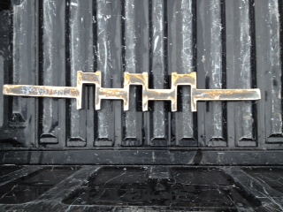 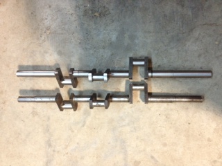 |
    
marion
New member
Username: marion
Post Number: 1
Registered: 03-2013
| | Posted on Wednesday, March 20, 2013 - 01:40 pm: | 


|
JB,
As always, still marveling at your work!
How did you get from the three throws in a plane of the plate, to the three 120 degree staggered crank throws? |
    
rogerd
Member
Username: rogerd
Post Number: 13
Registered: 01-2010
| | Posted on Wednesday, March 20, 2013 - 04:10 pm: | 


|
A former worker at the St. Lawrence factory told me that they did the cranks like JB. They then heated the main bearing area and rotated the shaft in a press of some kind until the proper degree offsets for the crank throws were achieved. |
    
jb_castagnos
Senior Member
Username: jb_castagnos
Post Number: 776
Registered: 07-2002

| | Posted on Wednesday, March 20, 2013 - 08:36 pm: | 


|
I measured the old crank, gave dimensions to my son, he drew it up on his computer, took it to work and sent it to the burn table. Water jet would have been nice but he gets the plate and cutting for $.85 lb, for $23 I couldn't go wrong. The material is 572-50, I think that's right, their better grade of plate. I straightened it by eye before starting, it wasn't critical, roughed out a 1.5", mains finish 1.250", flywheel and coupling are 1.125". I used a 3/4" wrench to scribe the crank and center punched it, this also was not critical , when I put it in the crank grinder I can move it like a 4 jaw chuck to center it, grind it, cut the end off and re center it in the steady rest. Next I chucked one side in the 4 jaw, center drilled the other. I then turned the first main round, it was pretty springy so next I went to the crank grinder and ground the center mains. I could now use the steady rest and turn the last main. 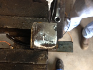 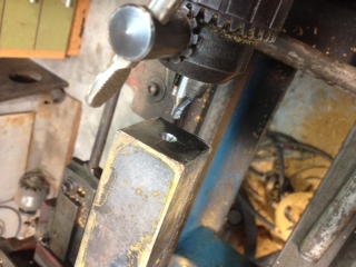 |
    
jb_castagnos
Senior Member
Username: jb_castagnos
Post Number: 777
Registered: 07-2002

| | Posted on Wednesday, March 20, 2013 - 08:44 pm: | 


|
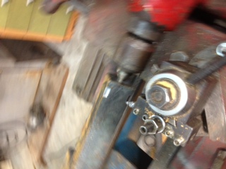 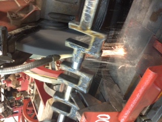 |
    
jb_castagnos
Senior Member
Username: jb_castagnos
Post Number: 778
Registered: 07-2002

| | Posted on Wednesday, March 20, 2013 - 08:47 pm: | 


|
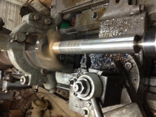
The crank is very springy, the steady rest in the middle made turning the last main easy. |
    
jb_castagnos
Senior Member
Username: jb_castagnos
Post Number: 779
Registered: 07-2002

| | Posted on Wednesday, March 20, 2013 - 08:52 pm: | 


|
When I first got into this hobby, I had just finished my boat, we attended the Pierre Part church fair. The church is next to the bay, the old timers talk of going to church in their boats. I had heard of Ulysse Comeaux, he lived down the bay across from the church, made his living repairing these old motors when they were in use. I told my friends about him and we decided to go visit. He was 92 years old at the time and legally blind, but was living by himself and managing well. We talked for a while about the old motors then he took us out to his shop. He pointed to a spot under the workbench and said there should be a rough cut crank down there. On the floor was a crank cut with both throws on one side, these 8hp Lockwood crankshafts should be 180 degree cranks. I asked about it and he said he had them torch cut out of a piece of 2X4" steel, heated them in his forge and twisted them to keep from having to buy 2X6" steel. He told us he started making the cranks and they were breaking in the middle where he twisted them, made a motion like a pepper mint stick with his fingers. He took a broken crank to Mr Nadler at Nadler foundry and told him about the cranks breaking, what was he doing wrong. Mr. Nadler looked at tit and said "you're twisting them while they're square, you're setting up a stress. Turn them round, twist them, finish turning". He said he never had a crank break after this. I asked him how he cut the keyways, a total of at least 6". He said he would scribe them while in the lathe and use a special little chisel, holding his hand up with his fingers bent back to describe it, he would chisel the keyways and file them. At this point I asked him how much he charged for a crank, he said $12. Before leaving I told him we had our boats in the bayou, something that hadn't been around for 30 years or so, he replied "I heard them, y'all have a 4, a 6, and an two 8hp", he was correct. |
    
jb_castagnos
Senior Member
Username: jb_castagnos
Post Number: 780
Registered: 07-2002

| | Posted on Wednesday, March 20, 2013 - 08:56 pm: | 


|
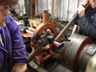
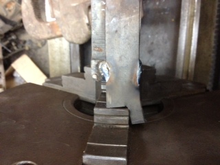
I installed the 3 jaw chuck on my big lathe, chucked the main in it, put the steady rest and live center on to the hold crank as sturdy as possible. I used a square to align one throw with a jaw on the chuck, then tacked a plate to the throw to try to keep it from rotating. The crank is to be twisted to align the next throw with the next jaw on the chuck, 120 degrees. Randy Landry helped me with the twisting, he's a quality control manager for a construction company, they never had a project like this, he was enjoying it and was a great help. He talked to the metallurgist they use to find out the best temperature to heat to and any other recommendations. 1700 degrees was what he recommended, don't heat any longer than necessary, don't cool it and don't wrap it, let it air cool. Cooling would make it brittle, wrapping would anneal it, heat treating shouldn't be necessary. In the last picture you can see it's been partially twisted, had to rotate the lathe to get another bite and reheat. 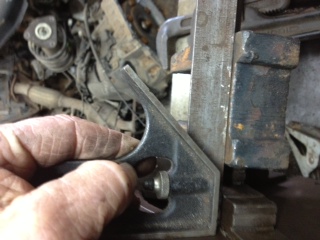 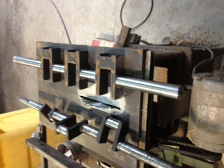 |
    
jb_castagnos
Senior Member
Username: jb_castagnos
Post Number: 781
Registered: 07-2002

| | Posted on Wednesday, March 20, 2013 - 08:58 pm: | 


|
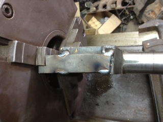
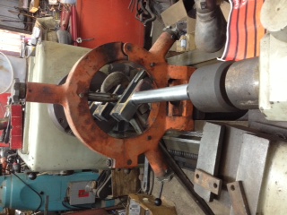
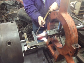 |
    
jb_castagnos
Senior Member
Username: jb_castagnos
Post Number: 782
Registered: 07-2002

| | Posted on Wednesday, March 20, 2013 - 09:01 pm: | 


|
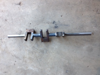
Randy and I are putting the final twist, then checking with the square. 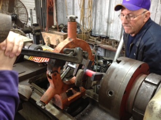
 |
    
jb_castagnos
Senior Member
Username: jb_castagnos
Post Number: 783
Registered: 07-2002

| | Posted on Wednesday, March 20, 2013 - 09:03 pm: | 


|
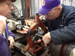
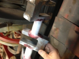
Checking alignment to the jaw of the chuck with a square |
    
jb_castagnos
Senior Member
Username: jb_castagnos
Post Number: 785
Registered: 07-2002

| | Posted on Wednesday, March 20, 2013 - 09:07 pm: | 


|
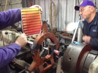
Using a color chart to determine the temp. |
    
jb_castagnos
Senior Member
Username: jb_castagnos
Post Number: 786
Registered: 07-2002

| | Posted on Wednesday, March 20, 2013 - 09:09 pm: | 


|
Here's a picture of 2 Lockwood Ash cranks, the factory crank is forged, the shop made one was cut from plate, likely by Mr Comeaux (Como). 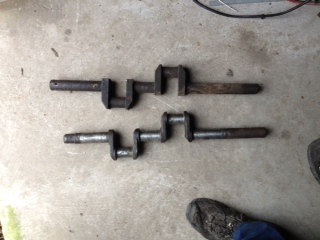 |
    
jb_castagnos
Senior Member
Username: jb_castagnos
Post Number: 787
Registered: 07-2002

| | Posted on Wednesday, March 20, 2013 - 09:14 pm: | 


|
It took a lot more torque to twist it than I anticipated, the first photo show this. I used a 1/8" plate for a stop, it was giving, I had to allow an extra .050" to compensate. I was glad my camera man Eugene noticed this before I removed the crank. I hoped to keep the crank straight enough to use after twisting, it was .150" over and I had it supported in three places. I was suprised to find out it was only .020" out after checking between centers. I was able to grind without even straightening. Randy dye checked it and no cracks showed.
More to come. |
    
bgoss
Senior Member
Username: bgoss
Post Number: 197
Registered: 12-2007
| | Posted on Saturday, March 23, 2013 - 12:38 pm: | 


|
I love this! Two guys out on the ends of big pipe wrenches. Low-tech is more my style. Thanks for posting JB. |
    
miro
Senior Member
Username: miro
Post Number: 686
Registered: 11-2001

| | Posted on Saturday, March 23, 2013 - 09:39 pm: | 


|
It's even more spectacular when you see it live and in person.
miro
ps the Cajun food is great |
    
robert
Senior Member
Username: robert
Post Number: 533
Registered: 07-2003
| | Posted on Saturday, March 23, 2013 - 10:09 pm: | 


|
Fascinating! Thanks for taking the time to photograph and post it. |
    
jb_castagnos
Senior Member
Username: jb_castagnos
Post Number: 788
Registered: 07-2002

| | Posted on Saturday, March 23, 2013 - 10:20 pm: | 


|
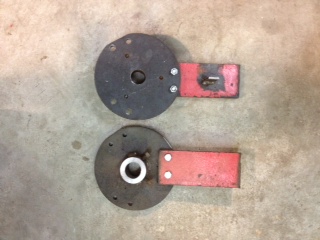
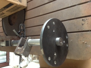
I bought the crank grinder last spring, finally got it set up and this is the sixth crank I've ground, still have a lot to learn about it.This long crank is flexible and takes special care. The grinder came with two steady rest and I plan to use both of them on the final grind, it's still .050" over but I want to fit it to the bearings, leaving it oversize if necessary. When setting up a crank to grind I would normally set the stroke on the dovetail ways, let the rod journal hang down to the center and swing the crank to dial it in at zero. With the square throws this wouldn't have been possible. I made two index plates, tacked them together and bored the center for the crank. I scribed a 4" circle for the stroke and divided it at 120 degrees for teh three crankpins, drilled center holes in both plates, welded on hubs with set screws. While the plates were together I milled a flat on both plates even with one of the center holes. The crank was placed on a flat table, the disc zeroed in with the flat spots and I used a square to align one of the throws. The crank can now be placed in and out of the grinder or lathe on centers without having to set anything and the stroke and 120 degree indexing will be correct. 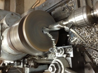
 |
    
robert
Senior Member
Username: robert
Post Number: 534
Registered: 07-2003
| | Posted on Saturday, March 23, 2013 - 10:39 pm: | 


|
Fascinating! Thanks for taking the time to photograph and post it. |
    
marion
New member
Username: marion
Post Number: 3
Registered: 03-2013
| | Posted on Wednesday, March 27, 2013 - 01:29 pm: | 


|
JB,
Thanks for answering my question. Very creative work!
Marion |
    
johnoxley
Senior Member
Username: johnoxley
Post Number: 165
Registered: 04-2010
| | Posted on Monday, October 31, 2016 - 07:18 am: | 


|
Fascinating thread - We replaced a 1985 wrought iron crank for a Plenty & Sons compound steam engine going into SY "Ena" because owner wanted a balanced job - 5" journal and 9" throw. Forging came from Singapore and was machined in Sydney. Crankshaft still going strong and has circumnavigated Australia. Then, at moment am part way through a new crank for a Stuart Turner D10 (7 mm. diameter x 10 mm. throw).
Then for really big built up cranks, look at http://www.dieselduck.info/historical/01%20diesel%20engine/Doxford/works.htm |
    
jb_castagnos
Senior Member
Username: jb_castagnos
Post Number: 1230
Registered: 07-2002

| | Posted on Monday, October 31, 2016 - 02:27 pm: | 


|
Thanks John, sounds like you're pretty deep into them also. |


