| Author |
Message |
    
J.B. Castagnos
| | Posted on Wednesday, February 25, 2004 - 09:41 pm: | 


|
I ran into a problem on the Fisherman, some teeth on the driven helical gear for the camshaft were rusted too thin to use, the gear would jam instead of advancing. I made a jig to machine the gear, it's in progress and looks like it will work. I machined a shaft to hold the gear blank in an index head. I figured that the gear had to rotate 25 degrees in it's 1 1/4" width. Using a protractor I drew lines at 0 and 25 degrees, at 3" out they were 1 1/4" apart. I made a swing arm and machined a section to hold cables, clamped it to a socket. The cables go around sheaves and are anchored to the mill parallel to the table, one left and one right. As the table is moved left-right the cables swing the arm and rotate the shaft. The gear has twelve teeth, the twelve point socket fits over a nut keyed to the shaft, this allows me to index the teeth by backing off the nut and advancing one slot. The picture may make this a little clearer if I can post it.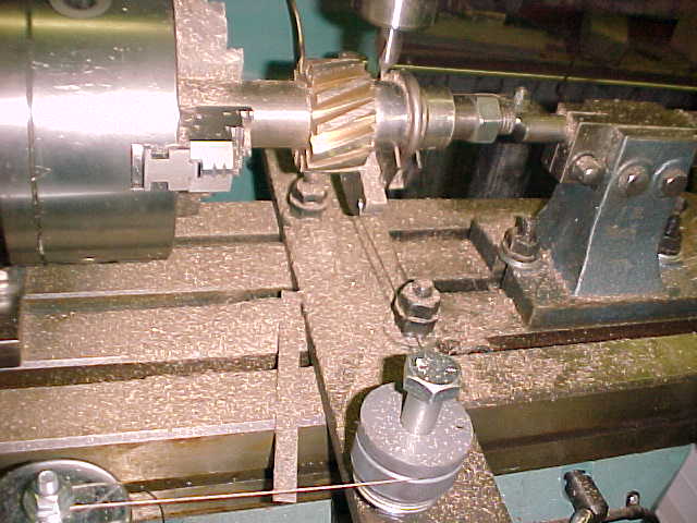 |
    
Keith
| | Posted on Thursday, February 26, 2004 - 08:46 am: | 


|
J B
You certinly are an ingenious individual. I have access to CNC equipment, that makes a job like that more straightforward. As a Tool & Die Maker by trade, I can appreciate the skills required to figure out how to accomplish the same result with limited equipment. You have the talent, ingenuity and spirit of the men who developed these motors 100 years ago.
Well Done,
Keith |
    
J.B. Castagnos
| | Posted on Thursday, February 26, 2004 - 01:16 pm: | 


|
Thanks Keith, this is a rewarding hobby. I've learned something about machine work, babbit pouring, pattern making, and boat building. I could have had the gear made but that would take the fun out of it. J.B. |
    
Paul [email protected]
| | Posted on Thursday, February 26, 2004 - 03:40 pm: | 


|
JB, have to agree with Keith. You are one of a kind genuis. |
    
Ernie
| | Posted on Friday, February 27, 2004 - 08:08 am: | 


|
Ditto from me on the commments above. The world of computers is making folks with your talent very hard to find! Like Keith said CNC equipment almost allows this kind of work to be done from a picture. Keith I said almost! I could not program one of your machines if I had to.
Great job! |
    
Tom Stranko
| | Posted on Friday, February 27, 2004 - 07:46 pm: | 


|
I had to read your description a few times for the setup to sink in. WHERE did this idea come from?
Did you cut each tooth all the way down before advancing to the next one? or did you do a little on each with many passes?
My hat is off to you!!
Tom |
    
rholcomb
| | Posted on Friday, February 27, 2004 - 09:13 pm: | 


|
what type of form tool did you use a single point tool cutting with one edge only and how did you do that curious bob..........
i have a brown and sharpe universal mill here with a universal dividing head tied to the table lead screw,i used a single point tool on a small fly cutter (single point tool) to generate the helix angle
good ole inginuity here
My hat is off to a unique idea bob... |
    
J.B. Castagnos
| | Posted on Friday, February 27, 2004 - 09:26 pm: | 


|
Tom, when I first looked at the gears I started thinking about making the drive gear, looks like a worm gear but with 6 teeth. I figured the driven gear would be easy to make, thinking it was straight teeth cut at an angle. The drive gear looks like it will be usable but the driven gear was to far gone. After studying it I realized the teeth had to curve around the gear. I pictured a similar setup with a flycutter shaped to cut the groove. That wouldn't work because as the gear advanced it would be widening the slot at both ends. I ended up using a 3/16ths end mill bit and cut slot to the correct depth. This cut in a few passes. The profile cutter is a reshaped center drill, it does ok until the last few passes, .010 at a time and slow travel. My first thought for rotation was to make a bellcrank and linkage. I klnew this would give a slight arc but figured I could live with it, Dick Gibbens couldn't. That's when I came up with the cables, the arm has a section machined to a 3" radius so it swings true all the way. The cables came from an old copying machine my 15 year old was tearing apart to salvage the good stuff. We're planning to make the trip to Calvert, but I don't think I'll have the Fisherman ready. Looking forward to meeting the rest of the group.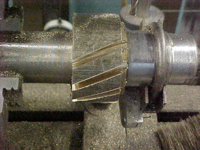 |
    
Tom Stranko
| | Posted on Saturday, February 28, 2004 - 09:44 am: | 


|
JB-
My tooling is about one step up from the village blacksmith so please excuse the (possibly obvious) questions: I now understand the cutting. As to the indexing, is it the case that what must be a "tail stock" is backed off and somehow a 12 point socket is fixed in place to it
-and always in the same alignment-and the chuck
is either rotated or the jaws are loostened to allow the work to be rotated to the next notch mating of the socket & nut, and the cutting resumed. It lookes to me like the mating of the work and the index device (nut) should never be disturbed. (thanks for the extra picture)
Tom |
    
Tom Stranko
| | Posted on Saturday, February 28, 2004 - 10:04 am: | 


|
The man who built the Wright Brothers 1903 4 cylinder 12HP, aluminum crankcase, make & break
engine was Charles E. Taylor. The historian-researchers at the Smithsonian have struggled to explain HOW Taylor did some of the machining on the engine given the limitations of what tools were available to him at the Wright's bicycle shop. The questions were finally answered when some sharp eyed person at the Ford Greenfield Village noticed that the cast iron blocks to raise up the head and tail stocks of his lathe
(thus allowing a 10" lathe to bore a hole over 5"
from the bed surface)were packed away in a barrel from the 1930's when Henry bought and moved the Wright's shop and home from Dayton to Michigan. Just to repeat what keith said already: this is the kind of spirit that our mechanical pioneers showed in abundance.
T |
    
J.B. Castagnos
| | Posted on Saturday, February 28, 2004 - 09:16 pm: | 


|
Tom, the swing arm that holds the cable is clamped to a 3/4" drive socket. I bored the threads out on a 3/4" nut and keyed it to the shaft with the same key that holds the gear. The socket fits over the nut to index the gear. After one tooth is cut, the nut behind the socket is backed off, the socket is slid back, and the gear rotated to the next spline. The cables and swing arm are always loaded and oriented. There was some slack in the socket to nut, but I always loaded it in the tighten direction. It repeated very well through the steps. The picture should help. 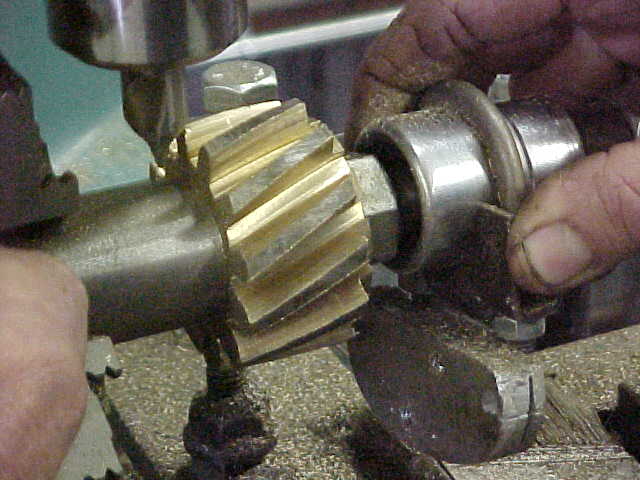 |
    
J.B. Castagnos
| | Posted on Saturday, February 28, 2004 - 09:32 pm: | 


|
Here's a picture of the finished gear in place, it works fine, turns smooth, little backlash. The old gear is in the picture. The Fisherman is one step closer, I have to rework the cam and go to the shed where I found it and look for the piston and rod, it should be there but there's a lot of parts to look through, if not I'll be looking for a piston in the 5" range, I can sleeve or bore it to make a piston work. I can make a rod also. The gear was a challenge but very gratifying. This is the first gear I've made, I recently bought a mill and it looks like it's going to be fun.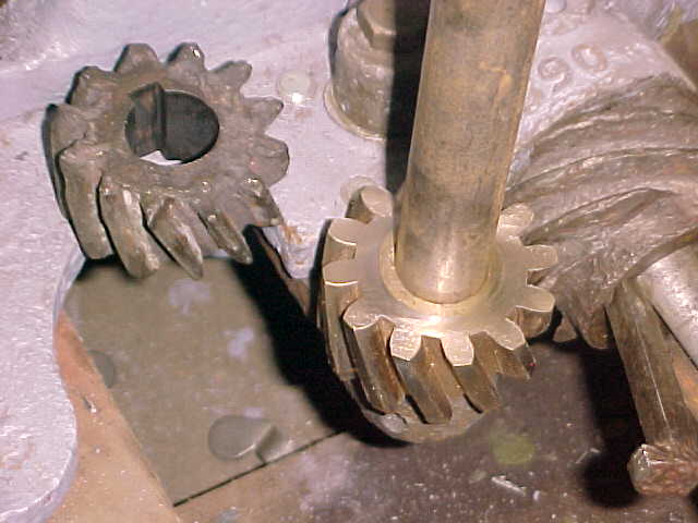 |
    
Dick Gibbens
| | Posted on Saturday, February 28, 2004 - 11:52 pm: | 


|
JB, as our old friend Phil Aucoin would say, "I'm glad I know you!" We have a great time with our hobby and you are at the point of the spear, always paying tribute to those built these machines by bringing thier monuments back from the dead to live forever! |
    
Tom Stranko
| | Posted on Sunday, February 29, 2004 - 03:12 pm: | 


|
I figured the socket had to be fixed in place somewhere in there but I could not see it until you put in the photo. Thanks again. The finished gear really looks great.
Dare I open up a can of worms and ask if that is a Chinese built mill? I was looking at a small one at Harbour Freight for about $250. I can't buy the milling adapter for my lathe for that price.
Tom |
    
Ernie
| | Posted on Sunday, February 29, 2004 - 04:43 pm: | 


|
The finished gear looks really nice! |
    
J.B. Castagnos
| | Posted on Sunday, February 29, 2004 - 08:36 pm: | 


|
The mill is an Enco Bridgeport copy, they were on sale for $2400 delivered a while back. We're in a drought area for used machinery, I was looking for a used Bridgeport. I had a small mill-drill before this, no comparison to the heavy machine. I want to thank ya'll for all the compliments, I had to let my cap out a couple of holes. |
    
Audie
| | Posted on Sunday, February 29, 2004 - 10:25 pm: | 


|
Beautiful job J.B. As for the web site for the club if you want I'll have the web master pull the info and pictures from here to post on the site. This is great material for the site. I'll also get the page about the buzz coil you developed and put it in there also. |
    
Richard Day
| | Posted on Monday, March 01, 2004 - 10:17 am: | 


|
J. B. Outstanding work. Makes me realize that I am not in the same class of a machinist you are. Looking forward to seeing you at CMM. |
    
jb_castagnos
Senior Member
Username: jb_castagnos
Post Number: 241
Registered: 07-2002
| | Posted on Sunday, May 29, 2005 - 11:40 am: | 


|
Keith Dupuy and Jamie Hurry came over yesterday and we ran the Fisherman, it's been many years since it's made noise. It was a little hard to get it started, great compression made it hard to pull over by hand. I would allow it to bleed down and pull it through, but it wouldn't hit hard enough to carry through. With a helping hand we gave it a good tug and it fired right up. I made a starting lever to fit the flywheel and was able to start it by myself. I tried reversing on the run and came close but it will take a little more practice. I didn't realize when you reverse you lose one stroke and the timer has to go over 180 degrees to fire tdc in the reverse direction. I had initially set the timer straight forward on tdc like a 2 cycle. It has to be pointing to the left for tdc in rh rotation, to the right for tdc in lh rotation. Because it's working off the cam at 1/2 speed, you only have to move the timer 1/2 the distance for max advance. To reverse, you have to hold the disconnect on the timer, advance timing, at near stop switch cam roller and let go of the disconnect. When it fires in reverse you have to immediatly swing the timer over 180 degrees. I'm practicing.
J.B. |
    
richarddurgee
Senior Member
Username: richarddurgee
Post Number: 777
Registered: 11-2001

| | Posted on Sunday, May 29, 2005 - 05:02 pm: | 


|
J.B.
You certainly have earned the satisfaction of hearing the "Fisherman" Run once again. A big part of this old engine fascination is to think and learn about or do something new or different, and you have certainly brought that to this board ! THANKS.
To understand the reverse rotation process I went back to this illustration
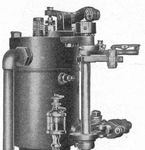
With A bit of thinking and drawing a few diagrams on paper the light bulb came on ! GREAT STUFF !
Richard |
    
andrew
Moderator
Username: andrew
Post Number: 1153
Registered: 11-2001

| | Posted on Sunday, May 29, 2005 - 05:25 pm: | 


|
JB,
Congratulations!!!
Any chance of posting a picture of it complete... maybe running... ?
Thanks, Andrew |
    
thomas
Senior Member
Username: thomas
Post Number: 267
Registered: 07-2002

| | Posted on Thursday, June 02, 2005 - 09:07 pm: | 


|
JB,
I would second Andrew!!
Sure would look great in GEM?
Tom |
    
J.B.
Visitor
| | Posted on Wednesday, September 15, 2010 - 11:42 pm: | 


|
Here's a link to a youtube video of the Fisherman running. It takes a little while to get co ordinated enough to reverse it on the spark when I haven't run it for a while, but it did OK here.
http://www.youtube.com/watch?v=6Q04DWoJnfo |
    
laurie_d
Senior Member
Username: laurie_d
Post Number: 64
Registered: 10-2009
| | Posted on Thursday, September 16, 2010 - 12:24 am: | 


|
JB, Many thanks for your message. Perhaps considering the work you have done and the outcome, a candidate for OME motor of the month/year? Meanwhile I'm interested in the small twin cylinder motor shown to the right of the black motor in the video clip. Can you tell me the make of that little twin? Regards Laurie (from down under). |
    
J.B.
Visitor
| | Posted on Thursday, September 16, 2010 - 08:29 am: | 


|
Laurie, the twin is Jamie Hurry's 5HP Lockwood Ash. It's a very early one with the base and cylinder cast in one piece, similar to the one in the thread linked below. Jamie's has the shaft timer like the one in the ad.
http://www.oldmarineengine.com/discus/messages/3433/2751.html#POST11168 |
    
laurie_d
Senior Member
Username: laurie_d
Post Number: 65
Registered: 10-2009
| | Posted on Friday, September 17, 2010 - 02:33 am: | 


|
Thanks JB, The twin LAs with the separate castings for each pot are very similar to our Blaxlands. Oh to have a 3 cylinder Blaxland like the 3 cylinedr LAs! Regards Laurie |


