| Author |
Message |
    
William Schaller
Senior Member
Username: billschaller
Post Number: 275
Registered: 12-2003

| | Posted on Wednesday, June 24, 2009 - 07:52 pm: | 


|
here is my ten inch variable pitch prop before I go and put it away.
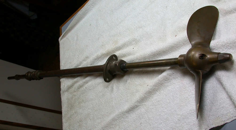
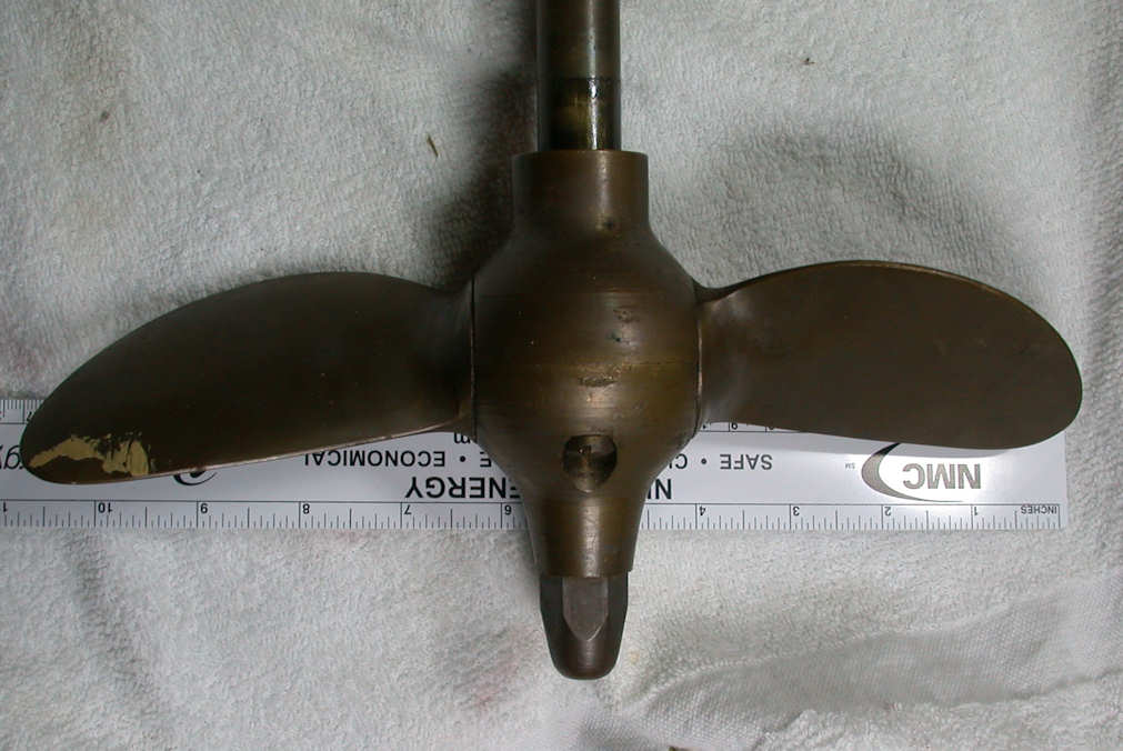 |
    
Steve Bennett
New member
Username: steve_b
Post Number: 3
Registered: 02-2015
| | Posted on Friday, February 27, 2015 - 06:10 pm: | 


|
Hi William, yours is similar to this 12 inch one I bought from a car boot sale a few months ago. I'm looking for one to go with my 3.5hp Real engine as the original was scrapped back in the 60's. I've seen a few pictures of how the mechanism should work on the outside but not the inside and need to make some parts. On the photo below I've just put some studding to hold the blades level but it would be really helpful if you or someone has a photo or drawing of how it should look. I'm missing it all including the handle. Regards, Steve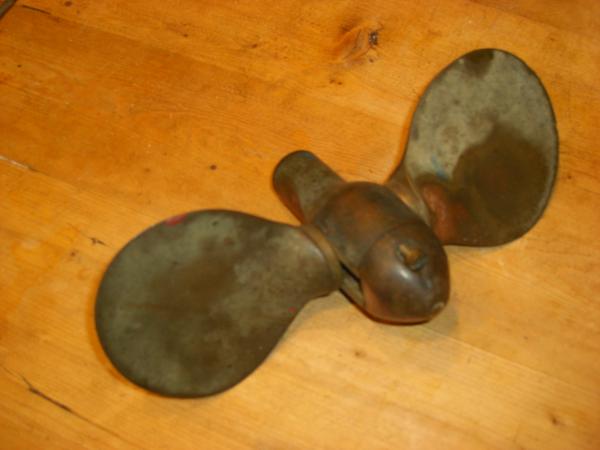 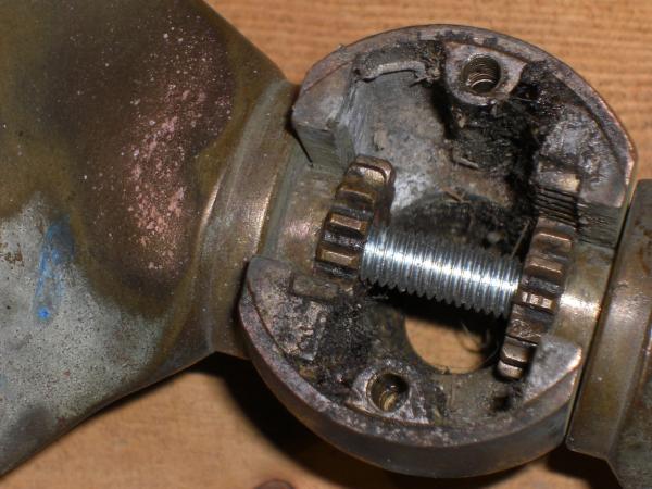 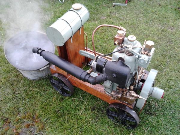 |
    
miro forest
Senior Member
Username: miro
Post Number: 803
Registered: 11-2001

| | Posted on Sunday, March 01, 2015 - 09:42 pm: | 


|
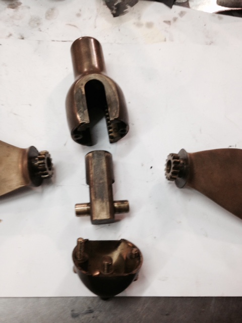
It loks like the inner control shaft moves the cross pin between the blades fore and aft. This causes the blades to rotate as they have a gear engaged with a rack .
SO, it means that there is a block in which the cross pin is held and the block is connected to the inner shaft that goes of to the engine coupling where there might be a slot in the outer shat again with a cross pin . A collar captures the cross pin and moves the inner shaft fore and aft.
JB - got any thoughts on this one?
miro |
    
J.B. Castagnos
Senior Member
Username: jb_castagnos
Post Number: 1033
Registered: 07-2002

| | Posted on Monday, March 02, 2015 - 01:48 pm: | 


|
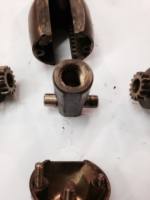
I have one like it. The center is 1.120" round, 2.635" long. The flats on each side are 1" across, machined all the way through. The flats where the pins are are .875" across, 1.5" deep. The pin is .5" X 2.00", centered .5" from the end. The threaded hole is 3/4" coarse thread.
 |
    
Steve Bennett
Member
Username: steve_b
Post Number: 4
Registered: 02-2015
| | Posted on Monday, March 02, 2015 - 02:00 pm: | 


|
Thanks Miro, I can understand how the prop end works as the hole in the prop is threaded to take the drive from the outer shaft. What I can't picture is how the inner shaft is controlled by the handle whilst the outer tube is spinning. I'm not normally a boat guy so haven't seen how these work before. I just saw this engine on ebay and thought I'd restore it.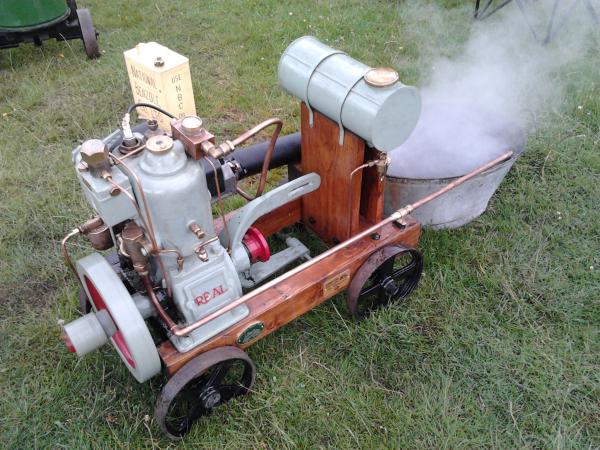 |
    
J.B. Castagnos
Senior Member
Username: jb_castagnos
Post Number: 1034
Registered: 07-2002

| | Posted on Monday, March 02, 2015 - 08:04 pm: | 


|
The inner 3/4" shaft would go into a flange mated to the one on the engine. The outer shaft has to have two stop collars about an inch apart. A floating collar between the stop collars would have two pins on it, one on each side. The lever would receive these pins, it would pivot at the bottom bracket and have a locking mechanism at the slot. Moving the lever would push the outer shaft back and forth, the inner shaft would be fixed to the engine. |
    
Steve Bennett
Member
Username: steve_b
Post Number: 5
Registered: 02-2015
| | Posted on Tuesday, March 03, 2015 - 02:16 pm: | 


|
Thanks JB, that makes sense now. I hadn't thought the inner one was taking the power. I've a friend with a lathe and milling machine in his garage so will have to have a play with lumps of brass and pipe that are lying around. |
    
J.B. Castagnos
Senior Member
Username: jb_castagnos
Post Number: 1035
Registered: 07-2002

| | Posted on Tuesday, March 03, 2015 - 07:27 pm: | 


|
Glad to help Steve, I see your engine is a 4 stroke, check the rotation. The inner shaft screws in and drives through the threads. If the engine turns CCW the threads should be LH, if not it will unscrew. |
    
Steve Bennett
Member
Username: steve_b
Post Number: 6
Registered: 02-2015
| | Posted on Wednesday, March 04, 2015 - 01:46 pm: | 


|
I did think of that and it's fine with normal RH threads. Would a 12 inch prop be too big for a 3.5hp engine? Not that it's going into the water or even a boat for that matter. |
    
J.B. Castagnos
Senior Member
Username: jb_castagnos
Post Number: 1037
Registered: 07-2002

| | Posted on Wednesday, March 04, 2015 - 08:30 pm: | 


|
These slow turning direct drive engines used larger props. Rule of thumb was a prop about the size of the flywheel. Because it's variable pitch it would be easy to tailor it to the engine |


