| Author |
Message |
    
jb_castagnos
Senior Member
Username: jb_castagnos
Post Number: 952
Registered: 07-2002

| | Posted on Friday, September 26, 2014 - 10:36 pm: | 


|
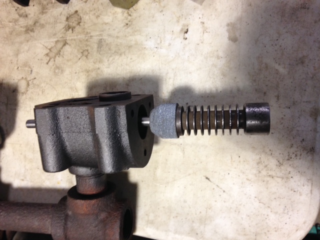
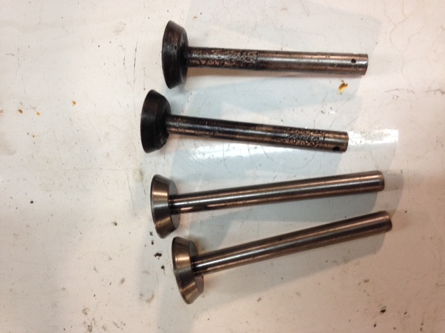
I got to work on the exhaust valves today. The old valves and seats were worn and rusty, decided to make new ones. Called McMaster yesterday, ordered 3/8" drill rod .002" over and a foot of cast iron bar, came in today. The .oo2 over was a snug fit, a light reaming gave a good fit. This is the first 60 degree valve I've ever seen, flat valves, 30 and 45 but not 60. I custom fit a stone and did the seats, one was rust pitted bad, the other came in quick. I bored the cast and parted off some disc, turned the stem for about a .004" press fit, heated the disc and nailed them in, bradded the top of the stem over. I rough turned the valves in the lathe, took them to the valve grinder. To my surprise the grinder was only marked a little past 45, had to match it to the 60 I cut in the lathe, I'll lap them and adjust the angle if necessary. They are still long, but there's no valve adjustment, I.ll cut the final length last. I have to make new rollers for the rocker arms and may do something with the rusty cam.
 |
    
richarddurgee
Senior Member
Username: richarddurgee
Post Number: 3379
Registered: 11-2001
| | Posted on Friday, September 26, 2014 - 11:49 pm: | 


|
*
J.B.
Those are really nice looking valves, yrs ago doing valve work I recall a 60 degree bottom valve seat angle on three angle cut seats, but have never seen or even read about a single 60 angled seat and valve ? learned something new today--appreciate the post !
* |
    
gregoryan
Senior Member
Username: gregoryan
Post Number: 118
Registered: 09-2004

| | Posted on Saturday, September 27, 2014 - 01:15 am: | 


|
Wonderful to see such restoration work on such a rare engine! Great Job!
Why 60deg??;,...
If you've ever had to dis assemble an engine because loss of compression, due to a random spot of carbon/ tar stuck to one side of the valve seating surface,,which cant be cleared with fluids down the plug hole, then this makes one [me] wonder how to design these mating surfaces to reject/ self-clean/ wear-off the offending foreign matter. Perhaps this is the idea; that such a steep angle does not keep compacting the carbon/tar, but instead rub it away!?
Of couse the angle cant be too steep, as a wedge-effect will occur - like the Morse taper. Perhaps 60 degrees is the safe limit, and; self cleaning?. |
    
jb_castagnos
Senior Member
Username: jb_castagnos
Post Number: 953
Registered: 07-2002

| | Posted on Saturday, September 27, 2014 - 05:55 am: | 


|
Thanks guys. The 60 degree on the mechanical exhaust looks to be more acceptable than the atmospheric intake. On the intake it looks like the valve would be hard to pull open, almost like a cork in a bottle. |
    
ernie
Senior Member
Username: ernie
Post Number: 1879
Registered: 01-2002

| | Posted on Saturday, September 27, 2014 - 07:01 pm: | 


|
I have an Associated air cooled stationary in my shop right now that I am putting together for Dick Day. It has 60 deg seats.
Seems to me there was something else I worked on years ago that had them too.
Anyway NICE work JB! |
    
jb_castagnos
Senior Member
Username: jb_castagnos
Post Number: 956
Registered: 07-2002

| | Posted on Tuesday, September 30, 2014 - 08:27 pm: | 


|
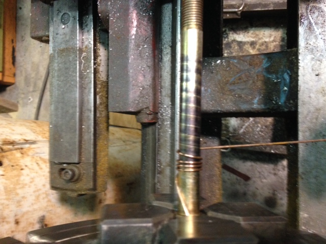
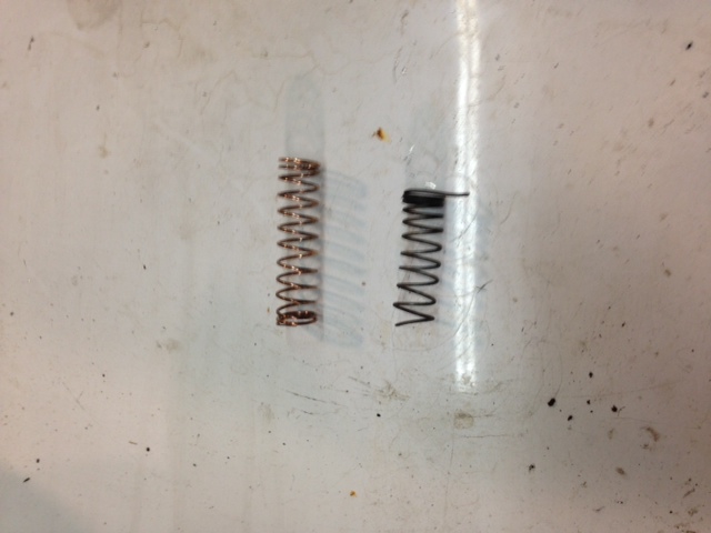
Sunday I went in and made the intake valves and ground the seats, worked out OK. I needed new springs, decided to wind some. I had the bronze spring wire, didn't want to spend a lot of time on a jig for two springs. I chucked a 7/16" bolt in the lathe, marked it 5 threads per inch with a felt marker. The wire was clamped under one jaw and the lathe was bumped while I wound it free hand following the mark. Came out OK, better than the ones they're replacing for sure. 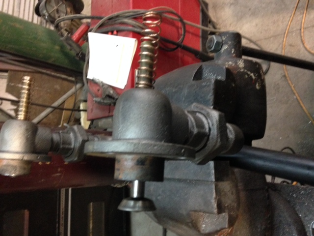
 |
    
jb_castagnos
Senior Member
Username: jb_castagnos
Post Number: 957
Registered: 07-2002

| | Posted on Tuesday, September 30, 2014 - 11:35 pm: | 


|
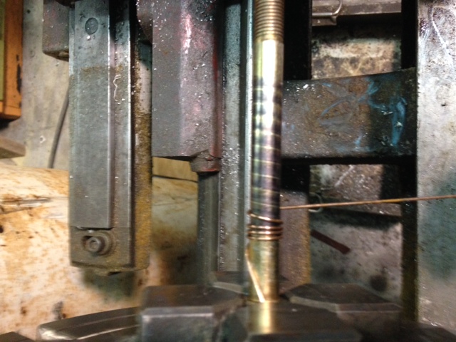
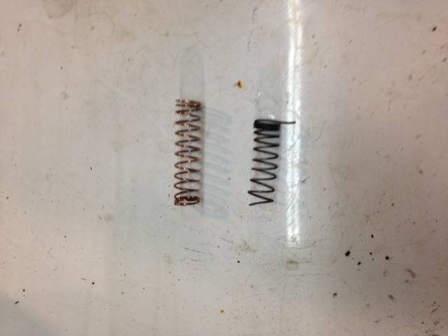
Sunday I went in and made the intake valves and ground the seats, worked out OK. I needed new springs, decided to wind some. I had the bronze spring wire, didn't want to spend a lot of time on a jig for two springs. I chucked a 7/16" bolt in the lathe, marked it 5 threads per inch with a felt marker. The wire was clamped under one jaw and the lathe was bumped while I wound it free hand following the mark. Came out OK, better than the ones they're replacing for sure. 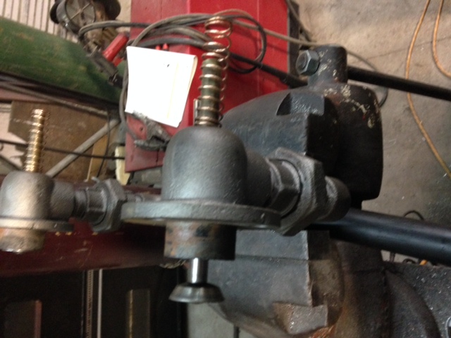
 |
    
ernie
Senior Member
Username: ernie
Post Number: 1881
Registered: 01-2002

| | Posted on Wednesday, October 01, 2014 - 08:24 am: | 


|
JB as usual "how do you think of these things"
Nice work!
Ernie |
    
jb_castagnos
Senior Member
Username: jb_castagnos
Post Number: 958
Registered: 07-2002

| | Posted on Thursday, October 02, 2014 - 10:37 pm: | 


|
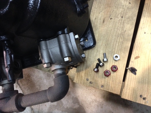
Thanks Ernie, I started making the high crown bolts and nuts, used 416 stainless hex from McMaster. Paul Gray and George Coates use this, makes nice bolts, easy to machine.
 |
    
jb_castagnos
Senior Member
Username: jb_castagnos
Post Number: 959
Registered: 07-2002

| | Posted on Tuesday, October 07, 2014 - 07:58 pm: | 


|
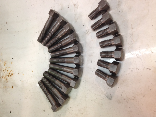
Finished the 3/8" bolts over the weekend, went pretty quick after I got going.
 |
    
gregoryan
Senior Member
Username: gregoryan
Post Number: 119
Registered: 09-2004

| | Posted on Tuesday, October 07, 2014 - 09:20 pm: | 


|
Wonderful to see such creations in progress! If only we all [ incl. myself] could be engine restorers. Thanks for showing details!
Is there a pic of this engine in it's entirety somewhere here? |
    
johnny
Senior Member
Username: johnny
Post Number: 483
Registered: 03-2006

| | Posted on Tuesday, October 21, 2014 - 06:51 am: | 


|
JB, Nice job on everything. you remind me of my father, there is nothing he can't do or make in his machine shop. You seem to be the same way. I have been a machinist for the past 40 years myself but I still have to ask Pop every once in a while how to do something. My fathers latest thing has been making helical gears on his manual mill. Now that takes a little brains.
Keep up the great work and I look forward to seeing your engine run. |
    
jb_castagnos
Senior Member
Username: jb_castagnos
Post Number: 963
Registered: 07-2002

| | Posted on Tuesday, October 21, 2014 - 01:42 pm: | 


|
Thanks Johnny, I'll post as I progress, working on the battery savers right now. I had to make a helical gear for my Fisherman, the post below shows how I did it, probably not 100 percent correct but it works.
http://www.oldmarineengine.com/discus/messages/1/2615.html |
    
johnny
Senior Member
Username: johnny
Post Number: 484
Registered: 03-2006

| | Posted on Wednesday, October 22, 2014 - 07:32 am: | 


|
Thank's for the link JB. Never seen it done with using cables. Going to email the link to my father. He made a sheet metal template and rolled it, so it was like a drum type tracer template. Don't ask me how he figured it all out but it worked. He was making a helical gear for the feed on a boring head he had bought a while back. |
    
klanger
Senior Member
Username: klanger
Post Number: 52
Registered: 03-2012

| | Posted on Thursday, October 23, 2014 - 05:07 am: | 


|
Great job JB, well done.
I always look forward to what your doing next to bring these old girls back to life.
Kev |
    
jb_castagnos
Senior Member
Username: jb_castagnos
Post Number: 974
Registered: 07-2002

| | Posted on Sunday, December 07, 2014 - 07:19 pm: | 


|
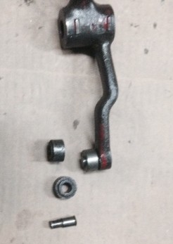
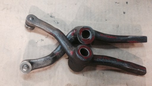
It's been quiet here lately, I've been working on farm engines, but I got a little done on the Racine this weekend. I made some new rollers for the cam follower-rocker arms. The old rollers were pitted and loose, made cast iron rollers and new pins.
 |
    
jb_castagnos
Senior Member
Username: jb_castagnos
Post Number: 975
Registered: 07-2002

| | Posted on Monday, December 08, 2014 - 08:22 pm: | 


|
Anyone else having trouble with post not showing up? |
    
ernie
Senior Member
Username: ernie
Post Number: 1910
Registered: 01-2002

| | Posted on Tuesday, December 09, 2014 - 09:28 am: | 


|
Seems OK to me |
    
richarddurgee
Senior Member
Username: richarddurgee
Post Number: 3413
Registered: 11-2001
| | Posted on Tuesday, December 09, 2014 - 11:09 am: | 


|
*
Have been away for a few weeks, this is first post
will see how it does ?
J.B. the photos of your work on the Racine are much appreciated, Its a level that most of us on here can't do but sure can admire, looking forward to seeing smoke out of it one day !
* |
    
jb_castagnos
Senior Member
Username: jb_castagnos
Post Number: 976
Registered: 07-2002

| | Posted on Tuesday, December 09, 2014 - 08:11 pm: | 


|
It's been strange, part of my message shows up in the topics on my home computer, nothing in the post. At work everything is normal. Last message in the post is October 23, under topics I can read "Is anyone having". |
    
jb_castagnos
Senior Member
Username: jb_castagnos
Post Number: 977
Registered: 07-2002

| | Posted on Tuesday, December 09, 2014 - 08:18 pm: | 


|
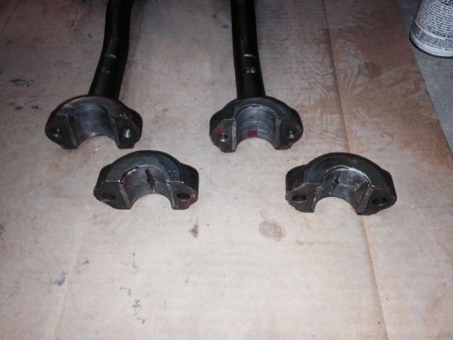
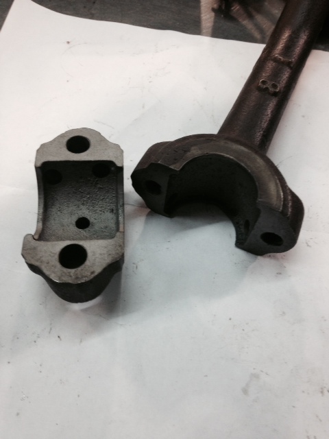
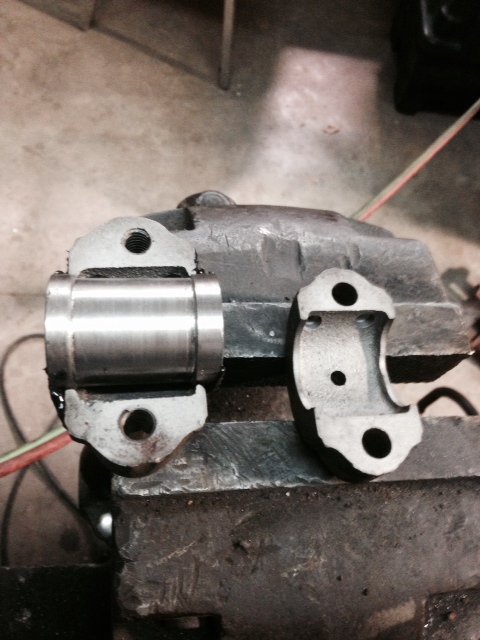
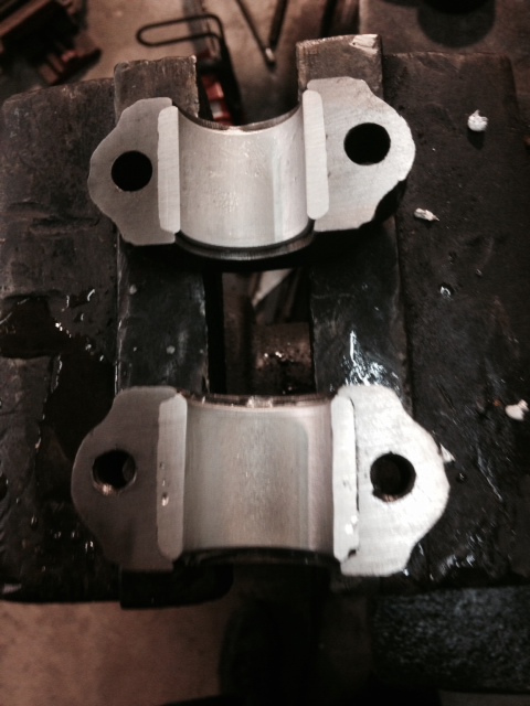
The rod bearings needed to be poured on the Racine Pierce inverted. I would have thought the rods were forged with the bends in them, but looking at the bearing area it looks like they were cast with a core to make a pocket for the bearings. The holes were bored through the thin sides, the pocket area was rough cast. I turned a little shaft 1.30" to match the bored area, turned the center section to 1.20" to allow me to bore them to fit the 1.250" shaft. I poured one of them this evening after work, looks good.
 |
    
klanger
Senior Member
Username: klanger
Post Number: 57
Registered: 03-2012

| | Posted on Wednesday, December 10, 2014 - 04:08 am: | 


|
Wish I lived closer.
Great job JB |
    
miro
Senior Member
Username: miro
Post Number: 781
Registered: 11-2001

| | Posted on Thursday, December 11, 2014 - 02:05 pm: | 


|
Well, Kevin, with the web you are as close as you need to be. I'm about 1/4 of the distance that you are, and for sure, I feel like I'm right there.
JB - you are not only a great guy, a great machinist, but one heck of a picture-taking-and-postng guy. It sure helps me get on with my projects and also to keep an eye out for stuff that othrers would see only as a piece of junk to be recycled into rebar.
miro |
    
jb_castagnos
Senior Member
Username: jb_castagnos
Post Number: 978
Registered: 07-2002

| | Posted on Thursday, December 11, 2014 - 10:55 pm: | 


|
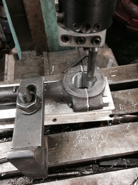
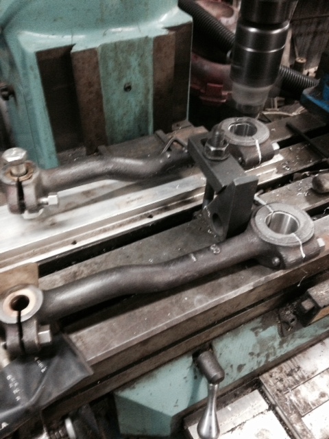
Thanks Miro, the i-phone really helps, never used to have a camera handy, Richard Durgee is probably the only reason I took pictures before, he would remind me. I made shims and bored the rods today.
 |
    
klanger
Senior Member
Username: klanger
Post Number: 58
Registered: 03-2012

| | Posted on Friday, December 12, 2014 - 04:42 am: | 


|
Very true Miro, but to be there and watch it happen..if it wasn't for the web none of us be any wiser to great work JB does. Keep on with pics JB. It's an invaluable record of what can be done.
Kev. |
    
jb_castagnos
Senior Member
Username: jb_castagnos
Post Number: 979
Registered: 07-2002

| | Posted on Friday, December 12, 2014 - 01:41 pm: | 


|
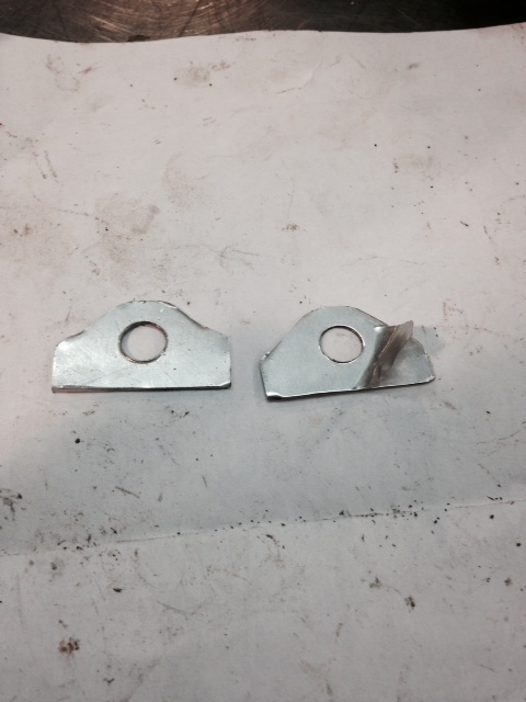
Thanks Kevin, the shims were made with aluminum peel away stock from McMaster-Carr. These are .002" per layer, .020" total.
 |
    
jb_castagnos
Senior Member
Username: jb_castagnos
Post Number: 993
Registered: 07-2002

| | Posted on Sunday, January 18, 2015 - 10:39 pm: | 


|
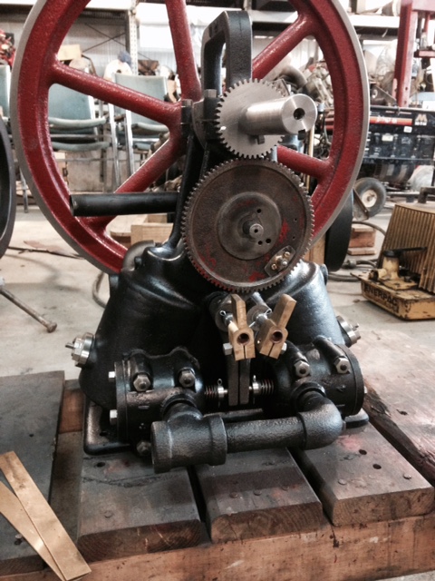
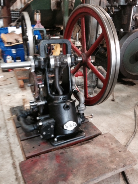
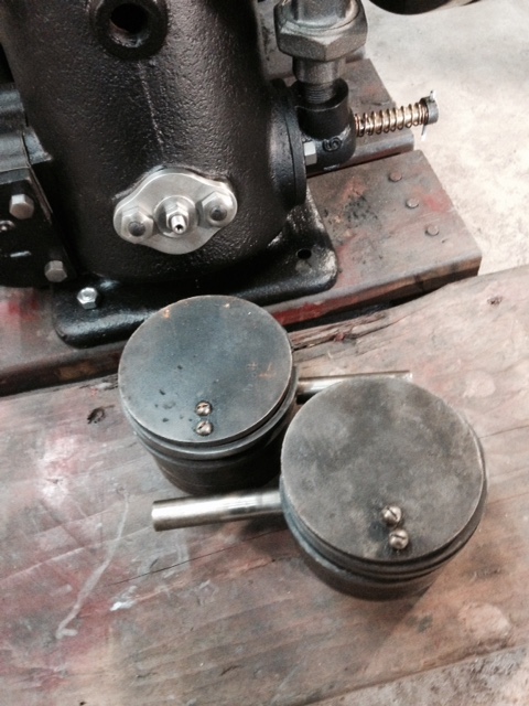
Had a chance to work on the Racine Pearce inverted this week. Dwayne's been patient, I'm happy to report some progress. I went in and made the gaskets and installed the valve cages this week. The intakes were finished, had to cut the exhaust to length for valve clearance, made new retainers, one was thick, the other narrow, have a matching pair now. The rocker arm pivot shafts were worn and the stepped down section was a little short for the battery savers. I made new shafts, a few thousandths oversize to fit the rockers. Installed them and put the rockers on, the RH rocker was out of parallel, looking at it I could see the babbitt was reamed crooked. They may have done this to compensate for an off square pivot, I didn't try it before. I melted the babbitt out, it was cored hollow like the connecting rod, the babbitt was thick and captured. I poured it full., drilled and reamed it 5/8", now I had to polish the shaft down for a fit. It lined up correctly when installed. I assembled the piston trip ignitors and temporarily installed them, they will have to come out to get the correct length for the contacts on the pistons, they were removed. 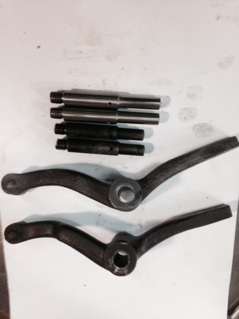
 |
    
jb_castagnos
Senior Member
Username: jb_castagnos
Post Number: 994
Registered: 07-2002

| | Posted on Sunday, January 18, 2015 - 10:42 pm: | 


|
Got it running today, here's a short video, more work to do but I was anxious to hear it.
https://www.youtube.com/watch?v=LGhmqnIuf3A |
    
klanger
Senior Member
Username: klanger
Post Number: 63
Registered: 03-2012

| | Posted on Monday, January 19, 2015 - 03:55 am: | 


|
Fantastic JB, well done. |
    
richarddurgee
Senior Member
Username: richarddurgee
Post Number: 3465
Registered: 11-2001
| | Posted on Monday, January 19, 2015 - 05:40 am: | 


|
*
J.B.
A lot of excellent work to get it this far, video really brings it to life, I,m sure its rewarding to see and hear it run so smoothly !
My nomination is in for this rare old Inverted engine to take its place in the Old Marine Engine hall of Fame !!
* |
    
keith
Senior Member
Username: keith
Post Number: 428
Registered: 02-2002

| | Posted on Monday, January 19, 2015 - 12:06 pm: | 


|
J.B., Dwayne should be one happy camper. Great Job.
Keith |
    
paulgray
Senior Member
Username: paulgray
Post Number: 150
Registered: 05-2003
| | Posted on Monday, January 19, 2015 - 05:30 pm: | 


|
Nice job JB! Those high crown fasteners and the dark background really make for a pleasing, quality machine. Always an inspiration to see your work, thanks |
    
ScottP
Visitor
| | Posted on Monday, January 19, 2015 - 05:45 pm: | 


|
Beautiful work, JB! Awesome workmanship, sir. |
    
raa
Senior Member
Username: raa
Post Number: 89
Registered: 02-2007

| | Posted on Monday, January 19, 2015 - 07:52 pm: | 


|
The usual wonderful workmanship. Looking forward to see it in the flesh this sprimg.
cheer
dick |
    
jb_castagnos
Senior Member
Username: jb_castagnos
Post Number: 995
Registered: 07-2002

| | Posted on Monday, January 19, 2015 - 08:45 pm: | 


|
It was running on one when I took the video, I went in this evening and worked on the ignitors. The blades that we had were not springy enough, I made new ones out of hack saw blades. John's engine was the first we tried with the piston trips, had some problems with the blades breaking at the mount. I made these paddle shaped, wide at the mount, a narrow waste, and a wide target. I think this will reduce the stress at the mount. The piston contact had a 1/4" wide button, I changed this to a rounded bull nose. Seems to be working well, after the video I idled it down low, ran steady.
Here's the video of it running on two.
https://www.youtube.com/watch?v=SRPwxTQZtB4 |
    
jb_castagnos
Senior Member
Username: jb_castagnos
Post Number: 996
Registered: 07-2002

| | Posted on Monday, January 19, 2015 - 09:05 pm: | 


|
Here's another of it running slow, I haven't had a lot of time to play with it yet, but it's coming around quick, starts very easy now. I used the old rings, when they seat in I'm sure it will do even better.
https://www.youtube.com/watch?v=9D65wPhpLE4 |
    
rbprice
Senior Member
Username: rbprice
Post Number: 493
Registered: 11-2001

| | Posted on Tuesday, January 20, 2015 - 04:41 pm: | 


|
JB - was there some specific reason why the engine created in that inverted position? |
    
richarddurgee
Senior Member
Username: richarddurgee
Post Number: 3468
Registered: 11-2001
| | Posted on Wednesday, January 21, 2015 - 12:12 am: | 


|
*
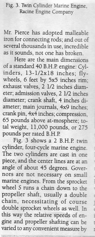
J.B.s Article
 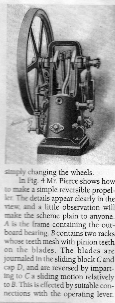
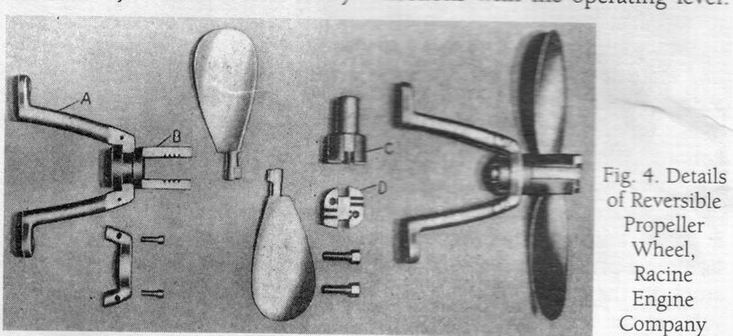
* |
    
richarddurgee
Senior Member
Username: richarddurgee
Post Number: 3469
Registered: 11-2001
| | Posted on Wednesday, January 21, 2015 - 05:19 am: | 


|
*
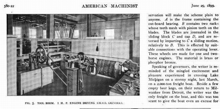
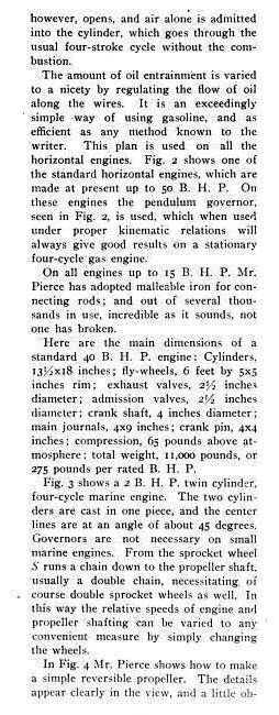
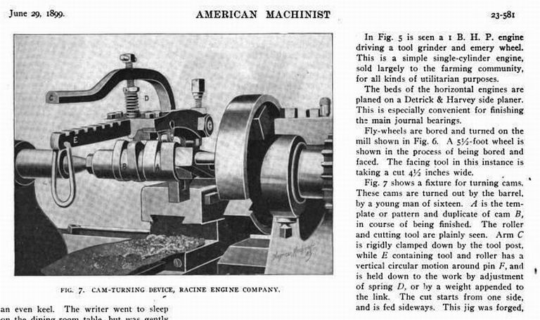
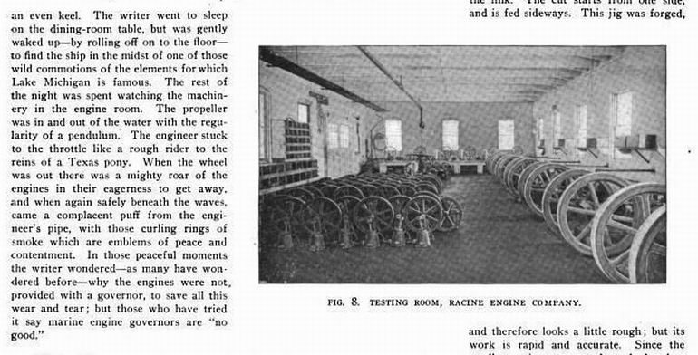
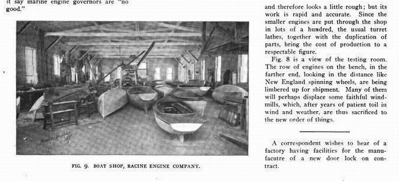
Racine Engine Company 1899
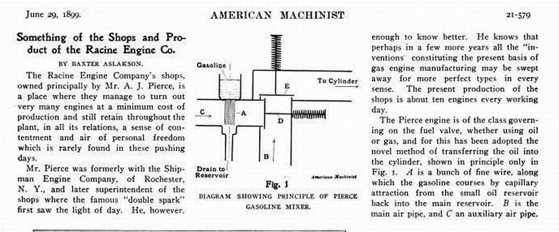
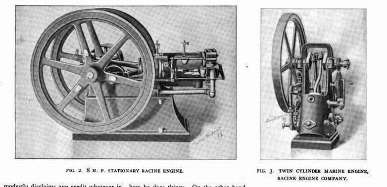
* |
    
rbprice
Senior Member
Username: rbprice
Post Number: 497
Registered: 11-2001

| | Posted on Wednesday, January 21, 2015 - 08:14 am: | 


|
Great bunch of information Richard. Thanks a bunch for adding it to JB's wonderful stuff. |
    
jb_castagnos
Senior Member
Username: jb_castagnos
Post Number: 997
Registered: 07-2002

| | Posted on Wednesday, January 21, 2015 - 09:06 am: | 


|
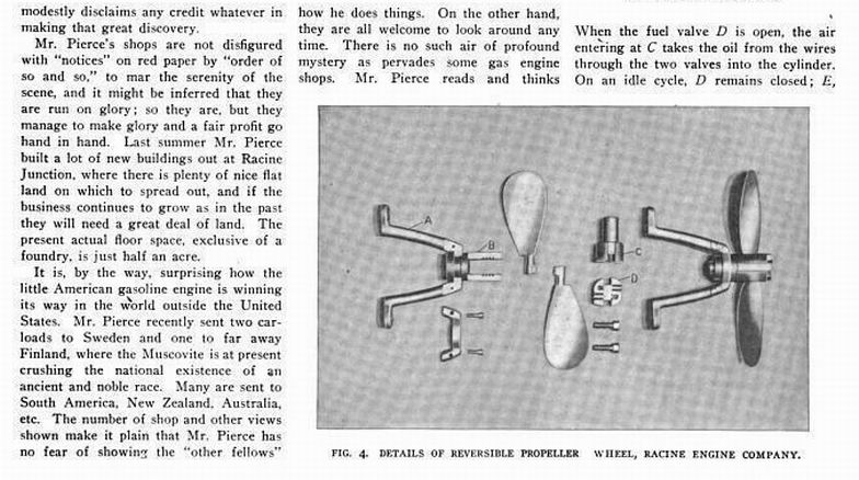
These engines were replacing high torque low rpm steam engines, the chain drive may have allowed them to under drive it and use the same shaft and propeller |
    
rbprice
Senior Member
Username: rbprice
Post Number: 498
Registered: 11-2001

| | Posted on Wednesday, January 21, 2015 - 10:26 am: | 


|
Thanks JB - and the text in one of Richards postings says just that "from the sprocket runs a chain that drives the propeller shaft"
Clever folks those old timers. |
    
jb_castagnos
Senior Member
Username: jb_castagnos
Post Number: 998
Registered: 07-2002

| | Posted on Wednesday, January 21, 2015 - 08:40 pm: | 


|
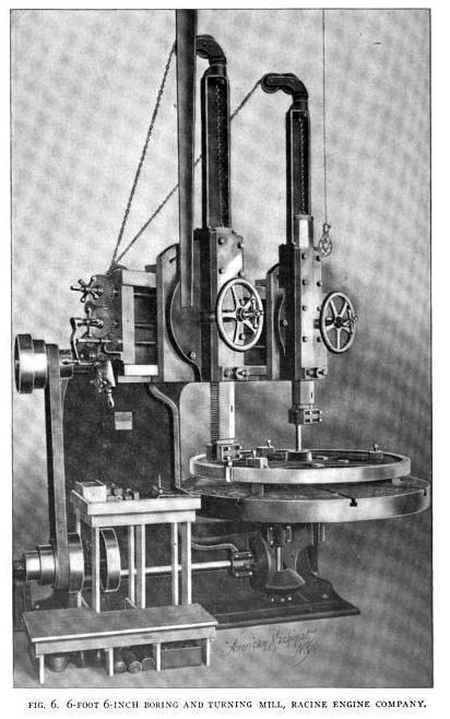
Thanks for posting the machinery pictures Richard. When I was honing the cylinder to install the sleeve I was trying to imagine what kind of equipment they could have had to bore these engines in 1895. It would take a heavy bar to reach that far and get a clean bore, that boring machine would do it. |
    
raa
Senior Member
Username: raa
Post Number: 90
Registered: 02-2007

| | Posted on Wednesday, January 21, 2015 - 09:38 pm: | 


|
Perhaps a horizontal boring bar would have been used. say a 2.5" or 3" bar
cheers
Dick |
    
billjr
New member
Username: billjr
Post Number: 1
Registered: 02-2005
| | Posted on Wednesday, January 21, 2015 - 10:33 pm: | 


|
I find the whole article interesting. especially the comment at the end about marine engine governors being "no good".
btw JB, fantastic job. |
    
johnny
Senior Member
Username: johnny
Post Number: 500
Registered: 03-2006

| | Posted on Thursday, January 22, 2015 - 06:55 am: | 


|
Thank's JB for taking the time to do all the photo's and posting them on the forum. I really enjoy reading & seeing the work of a skilled machinist & craftsman. It is people like you that help keep collectors/restorers interest in this hobby.
This has nothing to do with marine engines but another very interesting story and restoration like JB's all documented on the SmokStak forum. The story and restoration of a one of a kind Fairbanks 40hp stationary model "N" take apart engine. The story starts with going to get the engine that is located on the side of a mountain I believe in California somewhere. The engine was used to run a hoist for gold mining back in the early 1900's. It is believed the engine was hauled in by pack mules a piece at a time. It took the group of collectors 6 months to get all the parts of the engine off the side of the mountain and that was with the help of a helicopter. The engine is now almost ready to run. The story and restoration is four pages long and it will take you a while to read it all. See link below.
John Davis
http://www.smokstak.com/forum/showthread.php?t=61353&highlight=Fairbanks+40hp |
    
jb_castagnos
Senior Member
Username: jb_castagnos
Post Number: 999
Registered: 07-2002

| | Posted on Friday, January 23, 2015 - 09:51 pm: | 


|
The ignitor problem isn't solved yet, one of the hack saw blades failed. I replaced it with a piece of Briggs & Stratton recoil spring. On the piston I think I'll move the trip lever inward, use a longer blade. |
    
ernie
Senior Member
Username: ernie
Post Number: 1976
Registered: 01-2002

| | Posted on Saturday, January 24, 2015 - 01:38 pm: | 


|
JB the pic you posted on Jan 18th, is that another one in the background? |
    
jb_castagnos
Senior Member
Username: jb_castagnos
Post Number: 1001
Registered: 07-2002

| | Posted on Saturday, January 24, 2015 - 08:15 pm: | 


|
Yep. Dwayne Fuller had two of these, said if I rebuilt this one the other one is mine. I always liked these engines, saw the one in Lindsey's magazine years ago and thought it was one of the neatest engines ever. Didn't know what it was or that they still existed, didn't dream one day I'd own one. The two engines are similar but a lot of differences. The bore and valve cages are much larger on Dwayne's engine, the cam on his engine has two lobes, with a separation of maybe 22 1/2 degrees. The other engine has one lobe for both valves, John Smietana has an engine with the single lobe. When I was setting the timing on John's I had to settle for a happy medium, one valve closing a little before dead center and one a little after. The twin lobes corrected this. Also the flywheel on this engine has a belt groove in it, I assume to drive a low tension dynamo, I have one with a governor I plan to try on this it. |
    
ernie
Senior Member
Username: ernie
Post Number: 1979
Registered: 01-2002

| | Posted on Sunday, January 25, 2015 - 07:18 am: | 


|
Neat! |
    
jb_castagnos
Senior Member
Username: jb_castagnos
Post Number: 1008
Registered: 07-2002

| | Posted on Friday, February 06, 2015 - 10:58 pm: | 


|
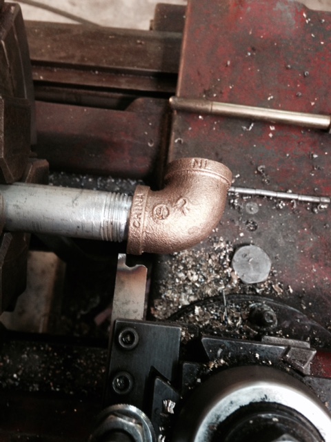
I started gathering brass fittings for the water plumbing on the inverted. I don't have any antique fittings so I ordered new. I had to do something about the China markings so I tried turning in the lathe to give them an old look, smoothed the castings a little also. The two street els I did freehand, decided to make a forming cutter for the others, I think they have a more appropriate look.
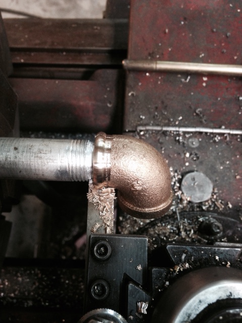
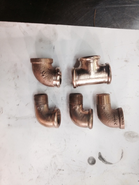 |
    
jim_parrott
Senior Member
Username: jim_parrott
Post Number: 75
Registered: 06-2009
| | Posted on Saturday, February 07, 2015 - 08:00 am: | 


|
JB,
Those look great. I have found that a needle scaler works good to rough up metal that is too smooth.
Jim |
    
richarddurgee
Senior Member
Username: richarddurgee
Post Number: 3492
Registered: 11-2001
| | Posted on Saturday, February 07, 2015 - 09:18 am: | 


|
*
About 30 years ago when I restored a 1906 Sterling marine engine I realized that the turn of the century brass pipe fittings were different than any I had ever used, would buy them at eng shows and my arm would go numb carrying them around, when ebay first started I found a pail of old brass fittings and bought them the man sent the pail and all !
J.B. Again your excellent work to preserve these old engines is well appreciated ! Good photos !
In referring to the above process of the fittings
I call it-
( mechanical artistry avoiding an anachronism )
* |
    
jb_castagnos
Senior Member
Username: jb_castagnos
Post Number: 1009
Registered: 07-2002

| | Posted on Saturday, February 07, 2015 - 09:48 pm: | 


|
I went in today and polished the fittings by hand with emery cloth, a "shoe shine". I buffed them on the wire wheel, heated with the torch to oxidize them a little. I'm pleased with the results, little things can make a project much nicer.
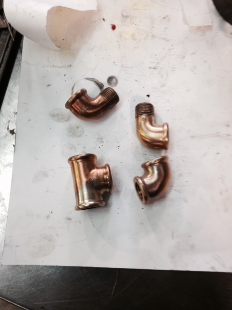 |
    
jb_castagnos
Senior Member
Username: jb_castagnos
Post Number: 1011
Registered: 07-2002

| | Posted on Sunday, February 08, 2015 - 09:40 pm: | 


|
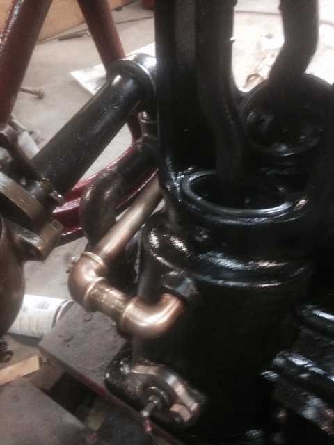
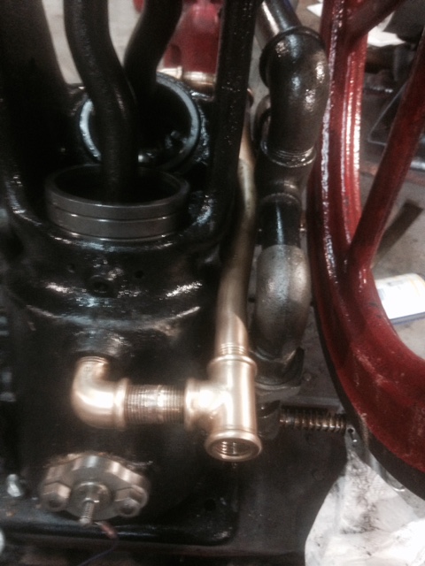
Started installing the plumbing today, it's a tight fit. It had a rubber hose with clamps when it came to me, I had to bend the 1/2" brass pipe to make it clear. I annealed the pipe, drilled 7/8" holes in some wooden blocks, sawed them to make saddles and bent it in the press. It bent a lot easier than I thought. I'm going to keep everything slightly uphill to help with the thermo-siphon.
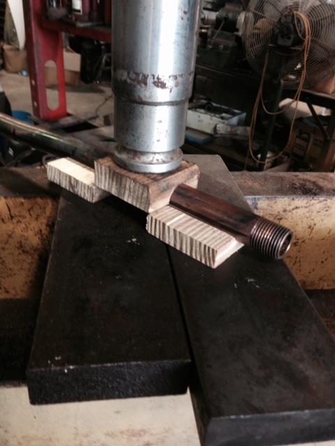
 |
    
keith_felder
Member
Username: keith_felder
Post Number: 15
Registered: 06-2012
| | Posted on Monday, February 09, 2015 - 09:02 am: | 


|
did you have to put sand in the pipe to bend it? |
    
bruce
Senior Member
Username: bruce
Post Number: 475
Registered: 07-2002
| | Posted on Monday, February 09, 2015 - 10:40 am: | 


|
no pipe union-how'd you do that?? |
    
jb_castagnos
Senior Member
Username: jb_castagnos
Post Number: 1012
Registered: 07-2002

| | Posted on Monday, February 09, 2015 - 01:38 pm: | 


|
No sand, it bent very easy, almost unnoticeable on the press. They make left hand pipe taps for a situation like this, that would have been the correct way to do it. It would have involved making a bushing for the tee, sweating it in, tapping it LH, threading the nipple LH in the lathe with the taper attachment. I cheated and cut the nipple, bored one side, turned the other so they would socket together. I ordered some ribbon silver solder to sweat them together. I've done them before, after polishing with emery they are hardly noticeable. Adding unions would have made it pretty bulky. |
    
bruce
Senior Member
Username: bruce
Post Number: 476
Registered: 07-2002
| | Posted on Monday, February 09, 2015 - 02:26 pm: | 


|
very clever stuff JB! |
    
richarddurgee
Senior Member
Username: richarddurgee
Post Number: 3497
Registered: 11-2001
| | Posted on Monday, February 09, 2015 - 02:37 pm: | 


|
*
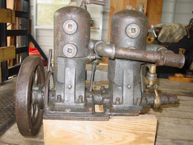
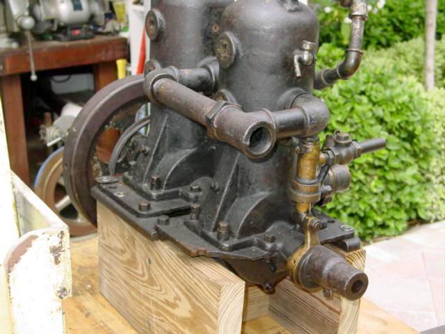
This 1906 Claude Sintz (Leader) twin I believe has
the original exhaust, it used the bushing in the tee method !
* |
    
keith
Senior Member
Username: keith
Post Number: 434
Registered: 02-2002

| | Posted on Monday, February 09, 2015 - 10:45 pm: | 


|
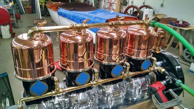
Hi Richard, I don�t think there is a bushing involved. They used a NPST thread (National Pipe Straight Thread) with a packing nut, on the one end of the pipe, and a conventional NPT (National Pipe Thread) on the other. You could thread the straight pipe far enough into the fitting, rotate the pipe and than thread the std thread into the opposing fitting.
Wrap the straight thread with packing thread and lock the nut. Not sure if I described the process in an understandable way but it is the process I had to use on the 4 cylinder Waterman on the supply and exit side of the cooling.
 |
    
richarddurgee
Senior Member
Username: richarddurgee
Post Number: 3499
Registered: 11-2001
| | Posted on Tuesday, February 10, 2015 - 01:01 am: | 


|
*
Keith
Your explanation of the straight pipe threads with a lock nut is very understandable.
I enlarged the photo of the fittings
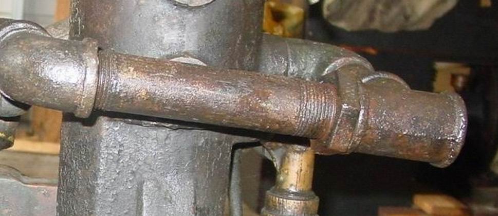
and it is evident that the threaded pipe at the lock nut is a straight cut and longer than a standard tapered pipe thread and assembled just as you explained !
This is a photo of my Tuttle and its very evident that this method was also used on these water pipes, straight pipe threads at lock nuts are much longer, cool straight pipe coupler fittings !
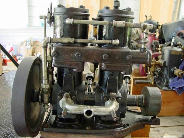
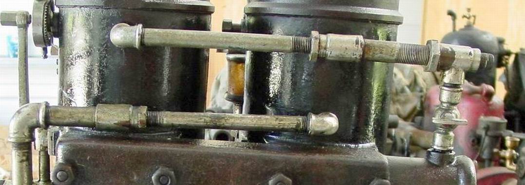
Appreciate the post and the lesson its a good day
when learning something new from these old marine engines !
* |
    
rbprice
Senior Member
Username: rbprice
Post Number: 501
Registered: 11-2001

| | Posted on Tuesday, February 10, 2015 - 08:00 am: | 


|
Not just for old engines: I have a straight pipe fitting on the water intake in the bottom of my Susquehanna River Tunnel boat. Can't take a picture as it is in its winter shed with 16 inches of snow on the roof. :^| |
    
jb_castagnos
Senior Member
Username: jb_castagnos
Post Number: 1013
Registered: 07-2002

| | Posted on Tuesday, February 10, 2015 - 08:04 am: | 


|
Hadn't seen that method Keith, I like it. |
    
jb_castagnos
Senior Member
Username: jb_castagnos
Post Number: 1014
Registered: 07-2002

| | Posted on Tuesday, February 10, 2015 - 09:13 pm: | 


|
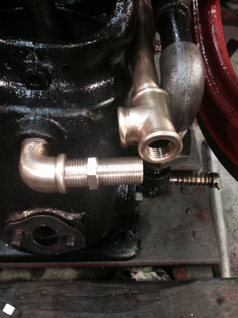
Here's my experimental version, straight on one side, taper on the other, hex in the center to tighten it. I have to make the packing nut, will try taking a 1/2" pipe tap and screwing into the T, marking the depth, grind the larger portion off. When I run it through it should straighten the threads.
 |
    
rbprice
Senior Member
Username: rbprice
Post Number: 502
Registered: 11-2001

| | Posted on Wednesday, February 11, 2015 - 08:13 am: | 


|
JB- is the straight thread left handed? And how do you spread the tee so you can get the straight thread started into the tee? |
    
jb_castagnos
Senior Member
Username: jb_castagnos
Post Number: 1015
Registered: 07-2002

| | Posted on Wednesday, February 11, 2015 - 10:54 am: | 


|
Bob, the straight thread is RH, 14 tpi. The tee is on a crossover so it is loose, the same fitting on both sides. That's the nice thing about this set up, you unscrew the straight until you have the spacing you want, start the taper and one is unscrewing while the other is screwing in, spacing stays the same. |
    
johnny
Senior Member
Username: johnny
Post Number: 501
Registered: 03-2006

| | Posted on Wednesday, February 11, 2015 - 11:44 am: | 


|
Jb, Does the internal straight thread in the T have a counter bore for packing material or is the nut your making just act as a jam nut? |
    
rbprice
Senior Member
Username: rbprice
Post Number: 503
Registered: 11-2001

| | Posted on Wednesday, February 11, 2015 - 12:01 pm: | 


|
OK - you screw the straight thread in till it bottoms, adjusting its OAL to get the spacing needed and then screw in the taper, which backs out the straight, then run the jam nut on the straight thread down against the tee.
Clever people these Cajuns. |
    
jb_castagnos
Senior Member
Username: jb_castagnos
Post Number: 1016
Registered: 07-2002

| | Posted on Wednesday, February 11, 2015 - 12:27 pm: | 


|
Bob, I can't take credit for this, just copied the originals from above post. Johnny, I talked to Keith about his, they had a chamfer in the nut to capture the packing. |
    
johnny
Senior Member
Username: johnny
Post Number: 502
Registered: 03-2006

| | Posted on Wednesday, February 11, 2015 - 02:14 pm: | 


|
Chamfer in the nut would work also, Just trying to figure out how they did it. Little tricks like that are good to know. |
    
rbprice
Senior Member
Username: rbprice
Post Number: 504
Registered: 11-2001

| | Posted on Wednesday, February 11, 2015 - 03:55 pm: | 


|
Somewhere in the long forgotten past a Designer was asked to come down to the assembly shop and explain how the blazes the guys were supposed to assemble the pipes that were on the drawing. Foreheads were slapped, strong words were exchanged, bosses had scowls on their faces and much thought was given to solving the problem.
If you look in a PERKO catalog you will find lots of fittings with straight pipe threads and you can find both taps and dies for cutting them on eBay which is where I got mine. |
    
robert
Senior Member
Username: robert
Post Number: 665
Registered: 07-2003
| | Posted on Friday, February 13, 2015 - 03:10 pm: | 


|
Nice work! The only thing worse than fugly modern pipe fittings is plated modern fastenings! |
    
rbprice
Senior Member
Username: rbprice
Post Number: 505
Registered: 11-2001

| | Posted on Friday, February 13, 2015 - 03:53 pm: | 


|
Is fugly a copyrighted word? |
    
richarddurgee
Senior Member
Username: richarddurgee
Post Number: 3509
Registered: 11-2001
| | Posted on Friday, February 13, 2015 - 06:42 pm: | 


|
*
RB,
It's A portmanteau.
A word from words blended together with less letters.
Such as
1. Smog -- Smoke and Fog
2. Motel -- Motor Hotel
3. Avgas -- Aviation Gasoline
4. Fugly is a street portmanteau-- Fuc---g Ugly
* |
    
jb_castagnos
Senior Member
Username: jb_castagnos
Post Number: 1018
Registered: 07-2002

| | Posted on Friday, February 13, 2015 - 08:06 pm: | 


|
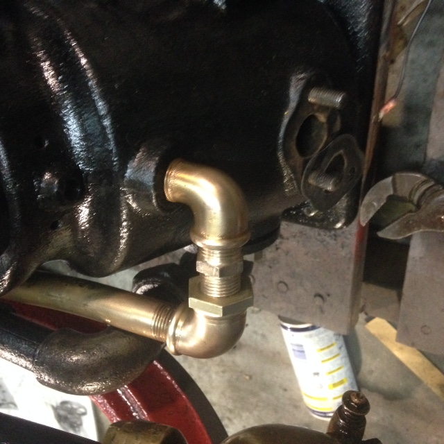
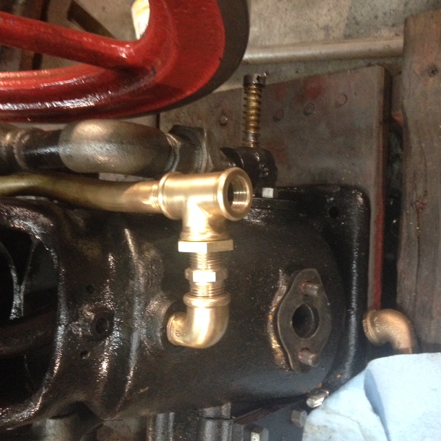
Finished the fittings and packing nuts today. I did a dry assembly. They fit well and look good, glad we had the earlier discussion.
 |
    
klanger
Senior Member
Username: klanger
Post Number: 65
Registered: 03-2012

| | Posted on Friday, February 13, 2015 - 09:55 pm: | 


|
What do you use or the packing?
Great stuff, learning every day. |
    
jb_castagnos
Senior Member
Username: jb_castagnos
Post Number: 1019
Registered: 07-2002

| | Posted on Saturday, February 14, 2015 - 12:58 am: | 


|
Keith said his had cotton string, I'll probably un- weave a piece of packng, cheat a little and put some liquid teflon on it also. |
    
rbprice
Senior Member
Username: rbprice
Post Number: 506
Registered: 11-2001

| | Posted on Saturday, February 14, 2015 - 09:25 am: | 


|
Thanks for the lesson Richard - the f word in not in my vocabulary so that did not occur to me. |
    
jb_castagnos
Senior Member
Username: jb_castagnos
Post Number: 1020
Registered: 07-2002

| | Posted on Saturday, February 14, 2015 - 10:57 pm: | 


|
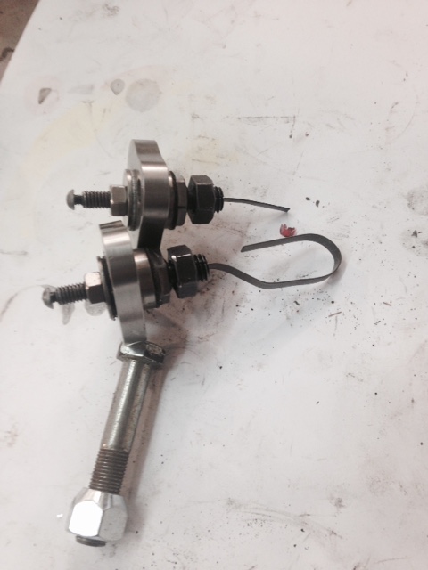
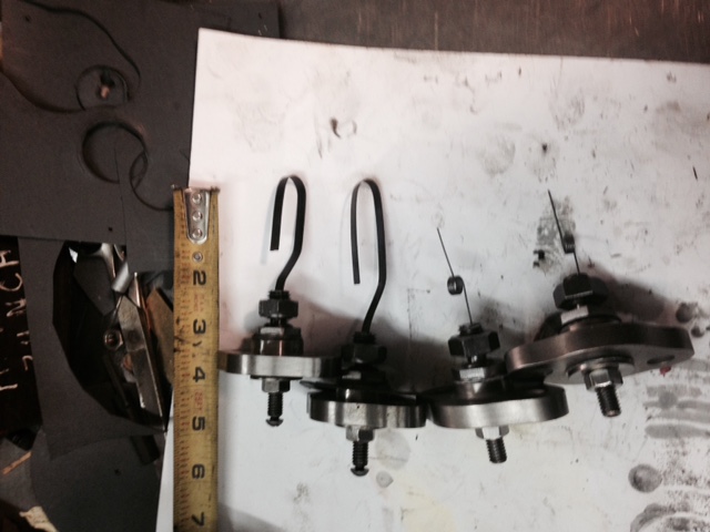
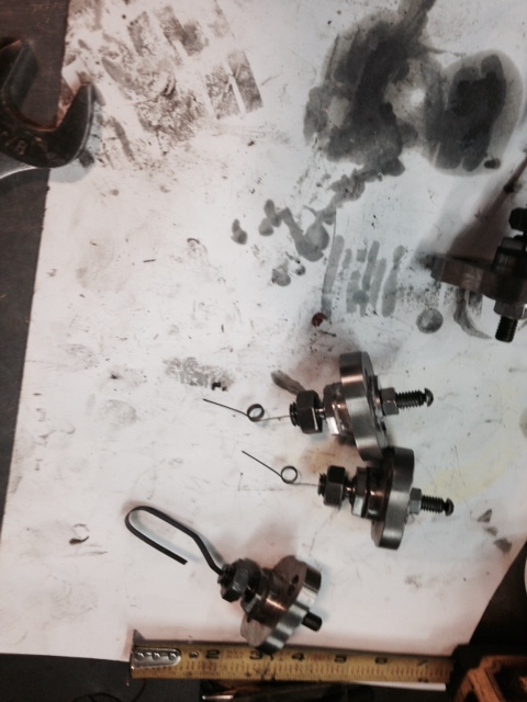
Been thinking about the ignitors on the Racine Pierce, trying different materials. Hacksaw blades didn't work, best material I've found so far is recoil spring from a Briggs & Stratton. The problem is the blade is too short, it ends up staying bent away from the piston, this let's it contact close to TDC, you have very little piton speed here, the ignitor doesn't draw an arc. It gets hard to start and misfires. Straighten the blade and it runs good for a while. I tried a different approach, looped the spring around, so far it's doing well.
 |
    
paulgray
Senior Member
Username: paulgray
Post Number: 151
Registered: 05-2003
| | Posted on Sunday, February 15, 2015 - 04:59 am: | 


|
JB, how about a piece of feeler gage stock? You can pick the thickness to get the right tension.or stiffness. You'll have to use carbide bits to drill it. |
    
keith_felder
Member
Username: keith_felder
Post Number: 20
Registered: 06-2012
| | Posted on Sunday, February 15, 2015 - 10:27 am: | 


|
i have some bandsaw blades, different sizes. they are not as hard as hacksaw. keith |
    
bruce
Senior Member
Username: bruce
Post Number: 477
Registered: 07-2002
| | Posted on Sunday, February 15, 2015 - 11:27 am: | 


|
I'm naive but seems like a small coil spring like a ball point pen spring would function here and not have breakage issues |
    
raa
Senior Member
Username: raa
Post Number: 93
Registered: 02-2007

| | Posted on Sunday, February 15, 2015 - 02:22 pm: | 


|
For whats its worth I see this as a balance between a short spring with high stress levels which will insure a good contact in a hostile environment and a long flexible spring with low stress levels but poor contact ability. Would it be possible to combine both using two lighter springs sort of like a leaf spring that way you keep stress levels lower and as the contact makes the spring rate would go up.
Cheers
dick |
    
j_ziegler
New member
Username: j_ziegler
Post Number: 2
Registered: 03-2012
| | Posted on Sunday, February 15, 2015 - 03:20 pm: | 


|
My thoughts were along the same line as Dicks except the second leaf maybe a little thicker, like an overload spring......j. |
    
rbprice
Senior Member
Username: rbprice
Post Number: 507
Registered: 11-2001

| | Posted on Sunday, February 15, 2015 - 04:17 pm: | 


|
JB - which part in the picture is the spring you are talking about - the short stubby one or the one that is curled back on itself? And when it fires what does the spark jump too. Also could you take the picture again with a scale in the picture?
Thanks |
    
johnny
Senior Member
Username: johnny
Post Number: 503
Registered: 03-2006

| | Posted on Sunday, February 15, 2015 - 06:27 pm: | 


|
JB I know you probably got more advice then you need but is there any way to extend the solid threaded rod further into the cylinder and have a smaller spring contacter? Even if you had to offset the rod for clearance and machine a flat on it for a small flat spring metal contacter. Maybe key the rod to keep it from turning. Seems like to me it would be more sturdy and more consistent on firing. If you have enough clearance between the piston and head to do it? Just a thought. |
    
jb_castagnos
Senior Member
Username: jb_castagnos
Post Number: 1021
Registered: 07-2002

| | Posted on Sunday, February 15, 2015 - 08:13 pm: | 


|
Paul, I've thought of using feeler gauge, don't know if it would remain flexible or work harden. It needs to be longer, the short reed bends too far.
I have about twenty minutes of run time on the long looped springs, it's still running well, far longer than any of the others would go without tinkering. I remved them and they still look good, tried some torsion springs, seemed very springy by hand, but started misfiring after about 30 seconds, removed them and they were bent down. I think a spring like this wold have to be loaded against a stop to maintain proper timing. Here's a youtube link of it with 20 minutes of run time.
https://www.youtube.com/watch?v=Tv7qoTlvzZI
 |
    
jb_castagnos
Senior Member
Username: jb_castagnos
Post Number: 1022
Registered: 07-2002

| | Posted on Sunday, February 15, 2015 - 09:17 pm: | 


|
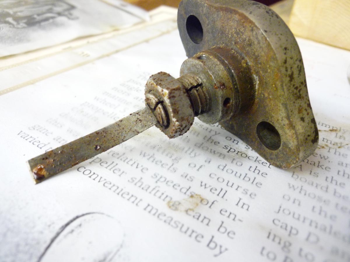
Bob, the spring is insulated, connected to a low tension coil. There is a contact, a bent piece of iron, screwed to the piston. It comes down and deflects the spring, making contact and charging the coil. When the piston moves away it breaks contact and draws an arc as the field collapses. To get a decent spark it has to be away from TDC, at TDC the piston is barely moving and won't draw an arc, as it moves away piston speed increases. Below is a picture of an original ignitor.
 |
    
rbprice
Senior Member
Username: rbprice
Post Number: 508
Registered: 11-2001

| | Posted on Monday, February 16, 2015 - 08:06 am: | 


|
This picture shows a collet designed to hold a strip Could the original part have been a Nichrome strip which would have excellent heat resistance and have maintained adequate springyness? It will work at temperatures up to 1800 F.
How much does the strip have to deflect when it engages the contact on the piston?
The Nichrome can take the heat: I am not sure about its ability to be constantly flexed. And then of course the question of where to get a small quantity to experiment with. Several companies sell the stuff: you could beg them for a sample :o) |
    
bruce
Senior Member
Username: bruce
Post Number: 478
Registered: 07-2002
| | Posted on Monday, February 16, 2015 - 02:42 pm: | 


|
Cannibalize an old toaster.. |
    
paulgray
Senior Member
Username: paulgray
Post Number: 152
Registered: 05-2003
| | Posted on Monday, February 16, 2015 - 04:31 pm: | 


|
Nichrome is pretty ductile stuff. I used to wind heating elements and it is not close to spring stock in terms of springiness. High carbon spring stock will hold up as long as the strain is within the elastic limit. |
    
rbprice
Senior Member
Username: rbprice
Post Number: 509
Registered: 11-2001

| | Posted on Monday, February 16, 2015 - 08:48 pm: | 


|
I think Paul is correct re the ductility of Nichrome but there is no question that a piece of spring stock would suffer by repeated heating in the combustion temperatures.
So the question remains - what did the Racine folks use in the first place? |
    
jb_castagnos
Senior Member
Username: jb_castagnos
Post Number: 1024
Registered: 07-2002

| | Posted on Monday, February 16, 2015 - 09:02 pm: | 


|
Bob, I think there's a misunderstanding, the spring steel is not damaged by heat, that would make it soft. It becomes quite hard, almost brittle, I'm calling it work hardened. The short length has to flex quite a bit, the long looped length has more room to flex without a sharp bending action. |
    
miro
Senior Member
Username: miro
Post Number: 796
Registered: 11-2001

| | Posted on Thursday, February 19, 2015 - 08:27 am: | 


|
How about this approach - picture is worth many words.
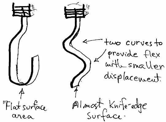
The challenge was to get a knife like edge ( not a point ) to contact the piston, yet make the amount of flex as small as possible, while providing good surface pressure.
I've seen some guys use a drop of hard surface weld to act as a contact that has good erosion prevention properties. I don't know if you could get that done on a knife edge, though.
That's my 2 1/2 cents (CDN) - 2 cents (US)
miro
See you all soon - I'm getting tired of the sneau up here |
    
jb_castagnos
Senior Member
Username: jb_castagnos
Post Number: 1025
Registered: 07-2002

| | Posted on Thursday, February 19, 2015 - 01:52 pm: | 


|
Miro, the ignitor is deflected by the piston, not compressed. The blade is horizontal, the piston approaches it vertically. An angle plate bolted to the piston contacts the blade, pushes it down, as it rises on the upstroke it draws an arc and fires. The problem with the short blade is that it would deflect for a while, then it would stay down. I could straighten it a few times but it would work harden and it wouldn't stay straight long. The longer looped blade has more room for deflection, it's still doing fine. |
    
jb_castagnos
Senior Member
Username: jb_castagnos
Post Number: 1047
Registered: 07-2002

| | Posted on Monday, April 06, 2015 - 10:16 pm: | 


|
Another step closer on the inverted, I made the battery savers this weekend, tried them out, looks like they will work. When I first saw the battery savers on Keith's engine I couldn't figure why they were needed, finally I realized the ignition was firing every stroke, a wasted spark on the exhaust stroke. This would kill the batteries twice as fast, important in the 1890's, these engines were being used for work and batteries were expensive. I also learned what direction the engine was intended to run, the battery savers would not be in time in the rotation I had been running it, had to re time the cam and run it in the other direction. Here's a link to youtube, they aren't in place, this was a trial run. By the way, still running on the hook shaped ignitors.
https://www.youtube.com/watch?v=OwcKZXzRpm0 |
    
ernie
Senior Member
Username: ernie
Post Number: 2049
Registered: 01-2002

| | Posted on Tuesday, April 07, 2015 - 08:20 am: | 


|
JB,
Real neat
Ernie |
    
johnny
Senior Member
Username: johnny
Post Number: 513
Registered: 03-2006

| | Posted on Tuesday, April 07, 2015 - 09:14 am: | 


|
Sounds really good JB, got her running fairly slow. video a little on the narrow side but engine looks and sounds great! |
    
richarddurgee
Senior Member
Username: richarddurgee
Post Number: 3559
Registered: 11-2001
| | Posted on Tuesday, April 07, 2015 - 10:25 am: | 


|
*
Battery savers look great ! Adds to the many mechanical motions to look at when the engine is running !
* |
    
jb_castagnos
Senior Member
Username: jb_castagnos
Post Number: 1053
Registered: 07-2002

| | Posted on Sunday, April 26, 2015 - 08:56 pm: | 


|
I delivered Dwayne's Inverted to his show Saturday, it ran great , he's got a little time to practice with it before he takes it to Coolspring. Now that his is done I figured I could try mine. I took the spark plugs out and put the piston trip ignitors in. Someone put aluminum pistons in this engine, it didn't have the contact on the piston. I used the recoil spring material, bent the last 3/4" up and rounded it off, let it hit the piston. It started right up and ran OK, not as good a Dwayne's , but I'll work on it. I have the dimensions on the pistons from a friends motor I repaired, plan to make a pattern and have some cast, will install the battery savers also. A youtube link below.
https://www.youtube.com/watch?v=yEo8kOmT85A&feature=em-upload_owner |


