| Author |
Message |
    
tharper
Member
Username: tharper
Post Number: 20
Registered: 12-2010
| | Posted on Wednesday, October 29, 2014 - 04:47 pm: | 


|
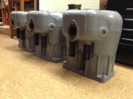
Well, now that we are settled in the new place and the shop (man cave) is up and running I have been able to work on the big Wisconsin.
The big news is that after 70 plus years the old girl is sporting a new and complete, functioning valve gear as opposed to those pretzel valves and springs it had before.
In addition work is progressing on the intake manifold - all castings are on hand and once I complete a critical fixture - machined as well.
Well, now that we are settled in the new place and the shop (man cave) is up and running I have been able to work on the big Wisconsin.
The big news is that after 70 plus years the old girl is sporting a new and complete, functioning valve gear as opposed to those pretzel valves and springs it had before.
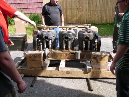
Here is a view of the beast loosely assembled for transport when we moved last year.
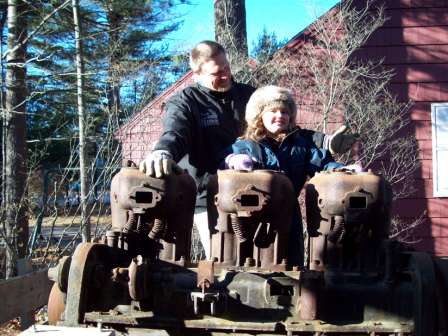
And.. a nostalgic view of how it use to look
Best regards,
Terry |
    
ldobbins
Senior Member
Username: ldobbins
Post Number: 160
Registered: 12-2002
| | Posted on Wednesday, October 29, 2014 - 05:00 pm: | 


|
Hi Terry,
The cylinders look great! Did you make new valves or find something modern with the same or close dimensions?
Maybe one of these days, I will get back to the pair of AM engines that I have.
Cheers,
Lew |
    
tharper
Member
Username: tharper
Post Number: 21
Registered: 12-2010
| | Posted on Wednesday, October 29, 2014 - 08:46 pm: | 


|
Hello Lew,
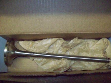
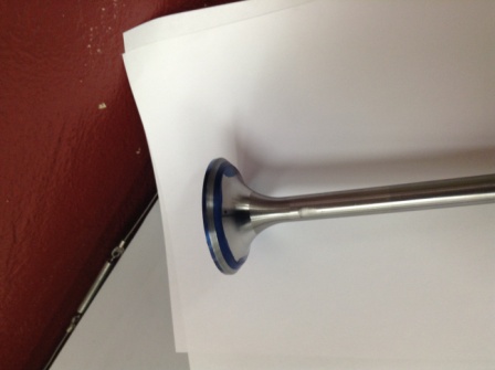
Sourced valve blanks from Carl Cummings Machine - they supply valves for EMD and GE locomotives. They are bi-alloy stainless steel - I had to turn the heads and keepers and cut to length. The stems are .557" as opposed to .50" for the originals but since I had to make new cast iron valve guides that wasn't big deal. The springs were scavenged by my friend Don from several different engines.
Valve blank as purchased
Finished valve
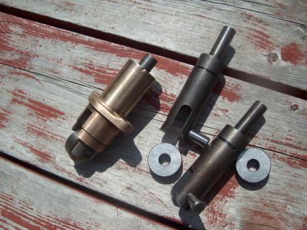
I had a complete set of lifters and guides but one was way beyond its goodness date so my friend Gene machined two new ones for me since that was before I had my own lathe and mill.
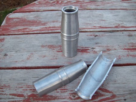
New valve shrouds cast and machined
 |
    
tharper
Member
Username: tharper
Post Number: 22
Registered: 12-2010
| | Posted on Wednesday, October 29, 2014 - 08:55 pm: | 


|
On another note here is one of the primer cups. They originally had a wood grip on the lever. I have generated the 3D model and 2D drawings for the pieces. I am thinking of having a set of parts CNC'd They are 1/4" NPT and measure 2-1/2" tall. It would be easy enough to run a few extra sets of parts if anyone is interested.
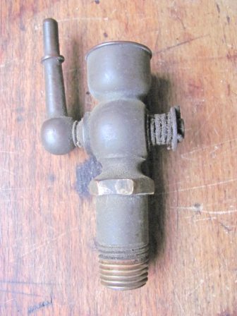
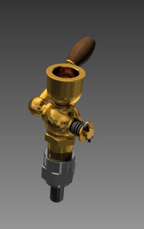
The primers screwed into a steel "primer cup stud" which was threaded for 5/16" and screwed into the top of the blocks.
Best regards,
Terry |
    
ldobbins
Senior Member
Username: ldobbins
Post Number: 161
Registered: 12-2002
| | Posted on Wednesday, October 29, 2014 - 09:43 pm: | 


|
Hi Terry,
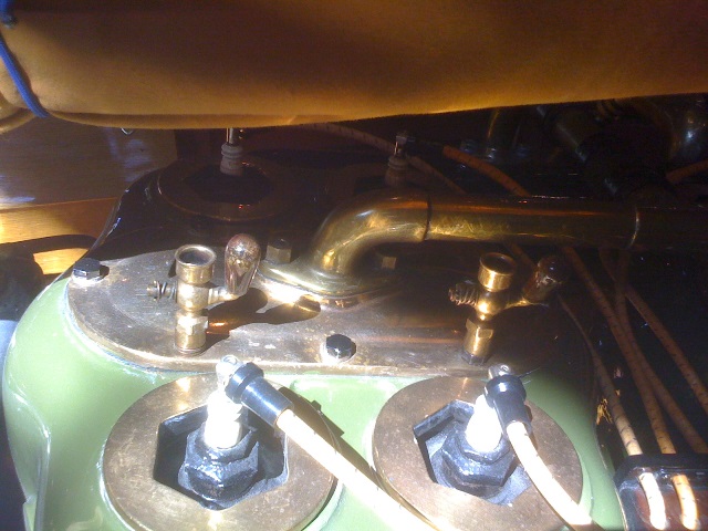
Looking great! Please let me know how much for 8 more priming cups. I have the 5/16" drilled studs on both of my engines. Here is a pic of the cups on a JRM. Note that the primer cup has an internal thread to screw down onto the studs.
Your adapters look great and functional, but what about these? I think, possibly, maybe, kinda sorta that these may be of original type. This JRM was pretty original when we restored it.
Cheers,
Lew
 |
    
tharper
Member
Username: tharper
Post Number: 23
Registered: 12-2010
| | Posted on Thursday, October 30, 2014 - 06:51 am: | 


|
Hello Lew,
That's very interesting.. I have never seen primers installed that way. As usual these old engines bring-up more questions than answers. I believe the style of adapter I have is original as well. The one I used as a "go-by" came from Don Johnson's PT which was used in a pumping station in Milwaukee. It was 100% complete but covered with silver paint when he acquired it back in the 70's. Apparently it had seen very little use as indicated by the hone makes still visible in the length of bores. Its now installed in his Lombard tractor. This style also appears in the parts catalog provided by Lombard.
Anyway, if you want I can modify my design to copy that used on the JRM just let me know.
I see the JRM was a duel ignition - I played around with setting the PT up that way but when a nice American-Bosch AT6 came my way for a very reasonable price I decided to go as factory original. I also scored the correct Stromberg M4 - the mag and the carb are both parts I had pretty much given up on. Now the wish list is down to the correct starter and generator.
Cheers!
Terry |
    
ldobbins
Senior Member
Username: ldobbins
Post Number: 162
Registered: 12-2002
| | Posted on Friday, October 31, 2014 - 12:37 pm: | 


|
Hi Terry,
Interesting indeed as we learn more. The outside thread cup makes more sense than a brass inside thread. I would think (I know, should not do that!)They (Wisconsin) would have purchased a standard off the shelf item. And I have not see internal thread cups before.
My 2 AMs are s spark engines as well. At one point, they were using Bosch DU-4 Dual/2 spark mags
Any other pics would be appreciated.
Cheers,
Lew |
    
tharper
Member
Username: tharper
Post Number: 24
Registered: 12-2010
| | Posted on Friday, October 31, 2014 - 04:54 pm: | 


|
Hello Lew,
Here is a photo of the primer studs I removed from my engine. The new ones are bit larger simply because I couldn't find the right size hex stock.
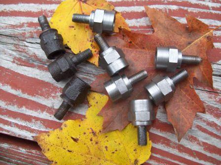
The neck was smashed off the original water pump and the impeller and shaft were way past their goodness date. We ended-up using parts from three different pumps and turning a new shaft and bushings.
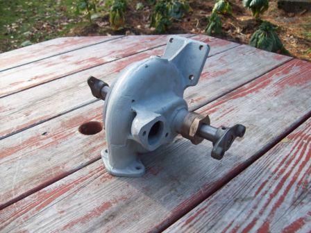
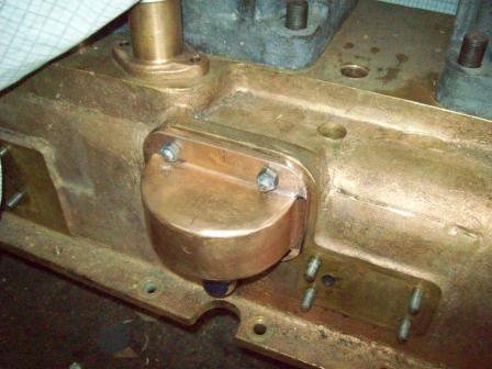
The oil pump is external and mounted on the oil pan. Drive to it is via a helical gear on the exhaust cam. Unfortunately the gear housing was smashed so I had to fabricate a pattern and cast a new one.
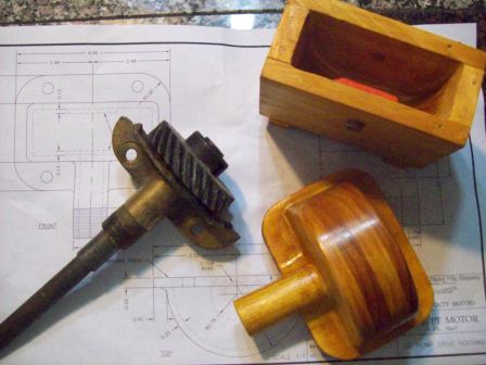
Here it is offered-up for a trial fit before final machining and finishing.
 |
    
tharper
Member
Username: tharper
Post Number: 25
Registered: 12-2010
| | Posted on Friday, October 31, 2014 - 05:14 pm: | 


|
If your not too bored here are some more...
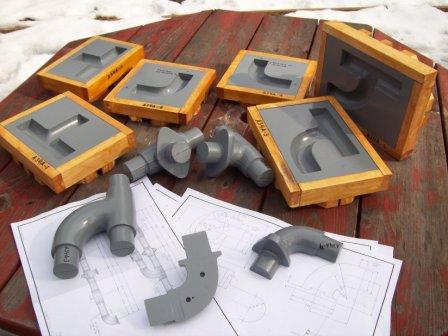
The intake manifold (at least on the engines used by Lombard) consisted of a series of bronze castings joined by brass pipes. Needless to say the manifold had disappeared a long, long time ago. Here is view of the patterns and core boxes I fabricated so I could replicate the original as close as possible. The core boxes are plaster of paris cast from male masters. The patterns themselves are all turned wood. I now have the castings on hand with only the combo tee/elbow pieces to counter bore.
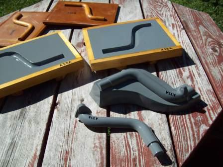
I also had to make a complete set of patterns and core boxes for the upper and lower water manifolds which were also bronze. These set is for the bronze pipe connecting the water pump to the radiator.
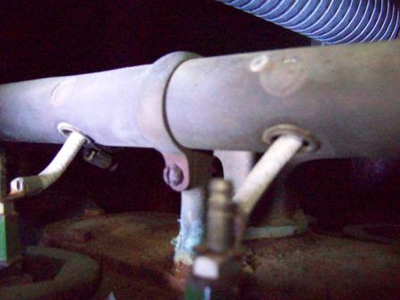
Lew, another interesting item are the brackets to hold the ignition wire tube. These are lovely brass castings that appear to be silver soldered into steel studs that, like the primer cup studs, screw into the top of the blocks.
Here is a very poor photo of an original
Best regards,
Terry |
    
jb_castagnos
Senior Member
Username: jb_castagnos
Post Number: 968
Registered: 07-2002

| | Posted on Friday, October 31, 2014 - 07:43 pm: | 


|
Excellent work, keep us posted. |
    
tharper
Member
Username: tharper
Post Number: 29
Registered: 12-2010
| | Posted on Sunday, February 15, 2015 - 08:38 am: | 


|
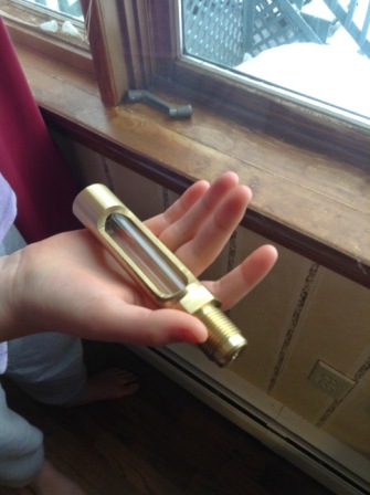
With the long, long cold spell we have been having I have not been in the shop much. However, I did finish fabricating the Oil Level Indicator gauge and have made some progress on a jig to hold a couple of the manifold parts.
The indicator gauge mounts in the top of the crankcase. A brass rod supported by a float tells you if you need to add to the 5 gallons of oil in the crankcase.
It came out OK but my novice machine skills are evident. Cutting the 3/4" gauge glass was more challenging than I thought. I tried using the lath method. Allegedly after scoring it with a carbide tool and applying heat it was supposed to pop apart by itself.
It didn't work that way. After one massive fail I managed to break it off somewhat clean but it has a crack (hidden in the photo) so I will have to try again.
Anyway... that's one more piece down and one fewer to go!
Best regards,
Terry |
    
ldobbins
Senior Member
Username: ldobbins
Post Number: 166
Registered: 12-2002
| | Posted on Sunday, February 15, 2015 - 12:18 pm: | 


|
Nice machining work Terry! Beautiful job,just like everything else on that engine.
Cheers,
Lew |
    
keith
Senior Member
Username: keith
Post Number: 436
Registered: 02-2002

| | Posted on Monday, February 16, 2015 - 10:38 pm: | 


|
Terry, Enjoy watching the progress. Keep posting your your efforts. Nice work.
Keith |


