| Author |
Message |
    
steve_hamel
New member
Username: steve_hamel
Post Number: 2
Registered: 08-2014
| | Posted on Wednesday, August 27, 2014 - 11:16 am: | 


|
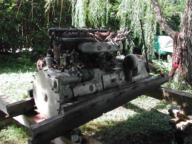
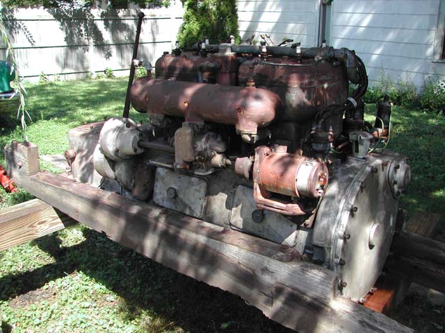
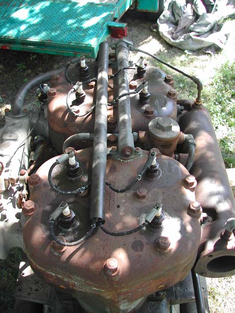
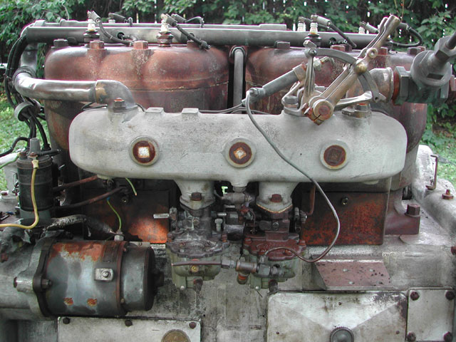
This Sterling has come under my care. Sadly the data plate is missing. Hoping the 'Sterling guys' can ID and help with tech info.
Bore stroke is about 5.5"x6.75". Carter BB-1 carbs.
12v North East Electric starter, generator.
Would also like to know typical use and installation for this type.
Many thanks,
Steve
   |
    
bruce
Senior Member
Username: bruce
Post Number: 445
Registered: 07-2002
| | Posted on Wednesday, August 27, 2014 - 08:37 pm: | 


|
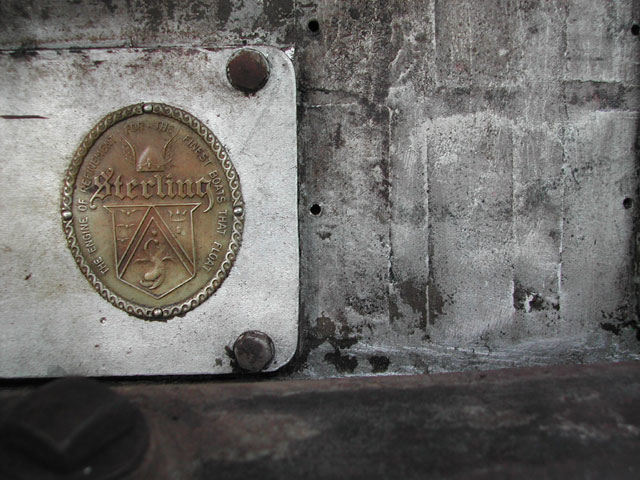
Ah Yes! I believe the oval badge on the Port forward crankcase inspection cover will state "The engine of distinction for the finest boats that float" . Twin distributor Dual ignition 4 cyl .Twelve volt.... Complete with F-N-R tranny... you lucky dog....Lou Dobbins; What year and model on this beauty??? |
    
ldobbins
Senior Member
Username: ldobbins
Post Number: 150
Registered: 12-2002
| | Posted on Wednesday, August 27, 2014 - 09:26 pm: | 


|
Greetings Steve,
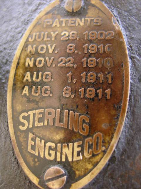
Thanks for the pics of you engine. She looks great. My guess is that she is mid 20s. Is that a Sterling brass oval logo plate affixed to the port side inspection cover? If it is not, what lead you this engine being a Sterling? I have a couple of questions to aid me in further identifying this engine:
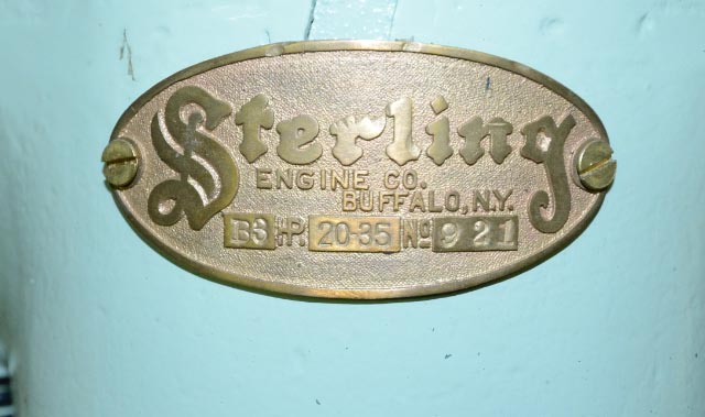
1. I have enclosed pics of 2 of the ID plates common to mid-teens to mid 20s Sterling engines. Are there screw holes matching these on the front of the number 1 cylinder above the flywheel and end of the rear cylinder above the timing gear case?
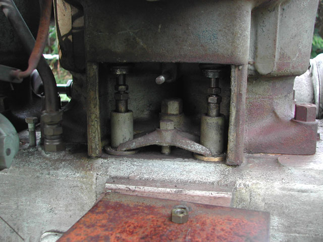
2. Are the cam roller followers (lifters) and valve stems exposed? Or under a cover with square side corners and a handle? Or in large tubes to contain oil and keep dirt out?
3. The man hole or inspection covers on the crank case look like Sterling. But most all of the T-head engines did not have a removable head. They were cast as part of the cylinder and then there were round threaded inspection/valve covers in the top of the casting. I suspect that this may be a very short lived production from the time they updated the model B (what family this looks like it is from) from single piece casting to a removable head. That said, are there any marks on the cylinder castings or the heads? The model B3 just for info was 5.5� bore by 6� stroke but I believe that the stroke grew a little more in later years.
4. What is the device between cylinders 2 and 3?
5. Do you have any better pictures of the engine. I am not sure what I am seeing for Distributors. Also would love to see more detail on the manifolds and reverse gear.
Let me know and see if you can provide any other pics.
Thanks,
Lew The west Coast Sterling Guy
  |
    
steve_hamel
Member
Username: steve_hamel
Post Number: 4
Registered: 08-2014
| | Posted on Thursday, August 28, 2014 - 12:10 pm: | 


|
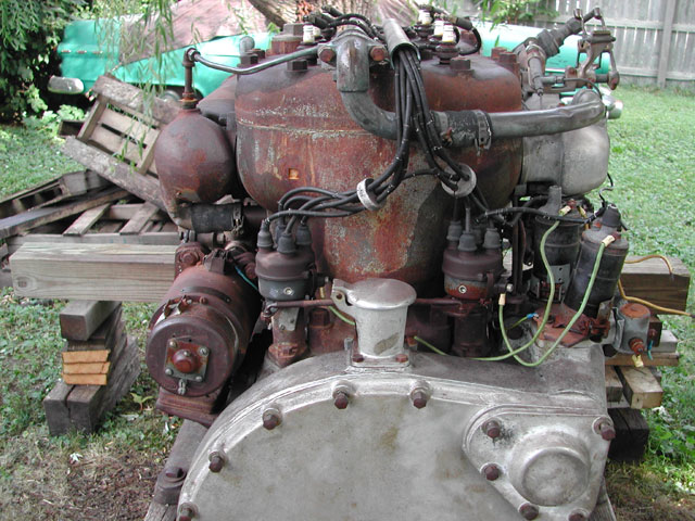
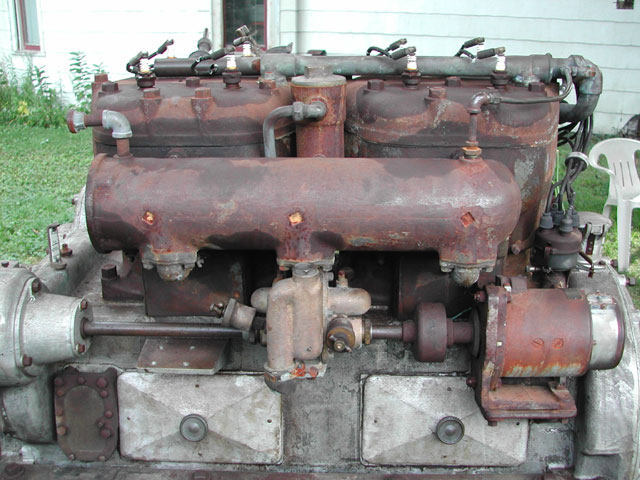
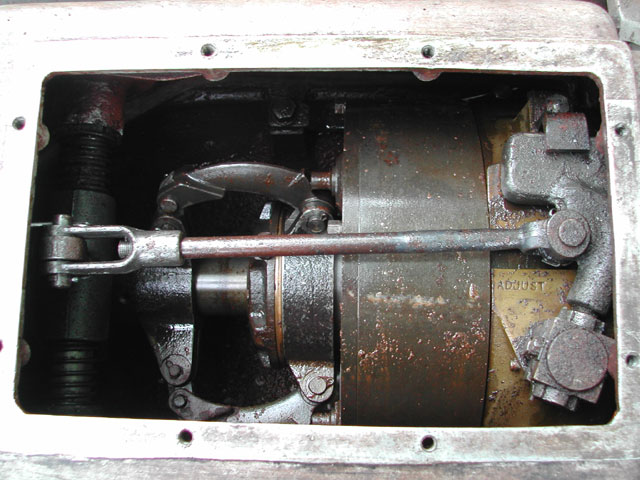
Here are more photos.
The device between the cylinders is an oil filter or water separator.
Roller followers are covered by a tin plate with brass nut.
The only number visible on the heads or cyl's is cast on EXP4872H.
Inside tappet covers is stamped SECO 2A434
Ring gear is stamped S226
Starter drive cover is stamped 2C448
Starter bendix is stamped with patent no's, latest is 1922.
Have not found any other markings... (yet).
Distributors are North East Electric.
Thanks for having a look.
Steve
https://www.youtube.com/watch?v=X8oy9sOfRCI
This is a W670 landing craft engine I've been working on.
      |
    
steve_hamel
Member
Username: steve_hamel
Post Number: 5
Registered: 08-2014
| | Posted on Thursday, August 28, 2014 - 12:30 pm: | 


|
Bruce,
Can you tell me more about the transmission?
Is it reversing or just in and out?
Would this have been direct drive or 'V'?
Thanks |
    
ldobbins
Senior Member
Username: ldobbins
Post Number: 151
Registered: 12-2002
| | Posted on Thursday, August 28, 2014 - 01:55 pm: | 


|
So I never asked. Is she free? What do you think it will take to get her running? And where did you find her?
Cheers,
Lew |
    
ldobbins
Senior Member
Username: ldobbins
Post Number: 152
Registered: 12-2002
| | Posted on Thursday, August 28, 2014 - 01:57 pm: | 


|
Greetings Steve,
The transmission is a standard marine reverse gear utilizing a set of steel and brass plates compressed together for forward, relaxed for neutral. Reverse is accomplished by the exposed band gripping the rotating drum and slowing it or stopping it. As the drum slows or stops, it forces a set of planetary gears to rotate about the pinion and cause it to run in reverse. The picture of your transmission looks like one of Sterling�s own design. Very similar to an earlier one I have. They also used paragon in the early days and Joes on some later and larger engines. This would have been used for direct drive, right hand rotation more than likely.
5.5� Bore by 6.75� stroke was a very common size for Sterling from around 1917 and into WWII. It was first introduced (I think) on the model F engines in all three types, FH, FM and FS (High Speed, Medium Speed and Slow Speed) in 4, 6 and 8 cylinder configuration. But the model F engine is as I mention yesterday, a one piece cylinder casting with brass screw on valve covers. The Chevron and Dolphin (model G series) were the first non-race engines that I thought had removable heads with overhead valves. But not a flat head with a removable head.
I am still digging to find when they built a removable head T-head engine. Other than a little plumbing, this looks so much like a model FS 4 cylinder engine. My guess is that it was an updated model F series from 1923 at the earliest and would have most likely been gone prior to 1930. Most all of the hardware I am seeing is also typical and used on the model F series. The twin carb setup is indicative of a higher speed motor as well. The FM and FH series were usually built on cast iron crank cases and not aluminum. Just as a reference, here are the specs from the late teens for a 4 cylinder FS:
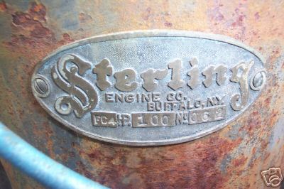
5.5� bore by 6.75� stroke, 641 CID, 90-100 HP at 1200-1400 RPM, 1250 lbs. Equipped with North East starter and generator. Distributors standard, Magneto upon request only. I have enclosed a pic of the engine ID for a model F commercial.
As I am very surprised and somewhat perplexed by this engine, I would love to hear from others on this.
Cheers,
Lew "The West Coast Sterling Guy"
 |
    
bruce
Senior Member
Username: bruce
Post Number: 446
Registered: 07-2002
| | Posted on Thursday, August 28, 2014 - 02:50 pm: | 


|
'55 Pontiac in the back ground?? OOps-"Engine of REFINEMENT for the finest boats that float". Fairly certain this would have been Direct drive instead of v-drive. No doubt a F_N_R transmission being from a boat. What say you Lou????? |
    
steve_hamel
Member
Username: steve_hamel
Post Number: 6
Registered: 08-2014
| | Posted on Thursday, August 28, 2014 - 06:02 pm: | 


|
Engine came from an auction of unrelated equipment in central Wisc. Trying to contact the seller and get some history.
There was quite a bit of water in the crankcase but surprisingly little corrosion. I poured diesel in the plug holes and gently levered the crank... It moved!
Two exhaust valves were stuck open but gave up with a veiled threat. Compression on three out of four.
Starter bendix had been messed with but I was able to make it function. I'll need a source for a drive spring. 1.312" ID, 2.375" OD, 7 coil, CCW, 2" bolt centers, for .375" bolts.
I'll clean the crankcase, figure out a way to pre oil, service carbs and ignition and it'll run.
I can detect only two positions for the shift lever. One couples direct with the crank, the other produces an intermittent reverse.
Once I understand the design I'll get it sorted.
56 Catalina Coupe. My very first car!
Stay tuned,
Steve |
    
ldobbins
Senior Member
Username: ldobbins
Post Number: 153
Registered: 12-2002
| | Posted on Thursday, August 28, 2014 - 06:50 pm: | 


|
Go to this address for some exploded views of a manual Paragon box. Hit next page to go through them.
http://www.marinegears.com/catalog/cat-pp-13.html
Your box is a forward, neutral and reverse box. You should feel the over center cam lock in forward, compressing clutch packs in the drum. You should also feel it lock all the way the other direction as an over center cam locks the drum band. Neutral is the floating position in the middle where the clutch packs are not compressed for forward and the band allows the drum to slip and turn freely. In the neutral position, prop creep is normal especially when the oil is cold as it grips between the clutch packs. When warm, it should be neutral with little creep if adjusted correctly.
Normal operation for maneuvering in the harbor is to be slipping it between forward, neutral and reverse as needed and seldom actually locking it into forward. One very rarely locks into reverse. As you move the lever back and forth it is the same thing as feathering a clutch in a car. Locking the box into forward will (if adjusted correctly and the plates are good) produce a 100% lockup between the engine crank and the prop. If not locked over center, you have an increasing amount of forward connection as you move the lever from neutral to locked forward, again, a clutch giving slipage.
Sounds like you got lucky on this one. Keep us posted!
Cheers,
Lew
The West Coast Sterling guy |
    
ernie
Senior Member
Username: ernie
Post Number: 1862
Registered: 01-2002

| | Posted on Thursday, August 28, 2014 - 08:16 pm: | 


|
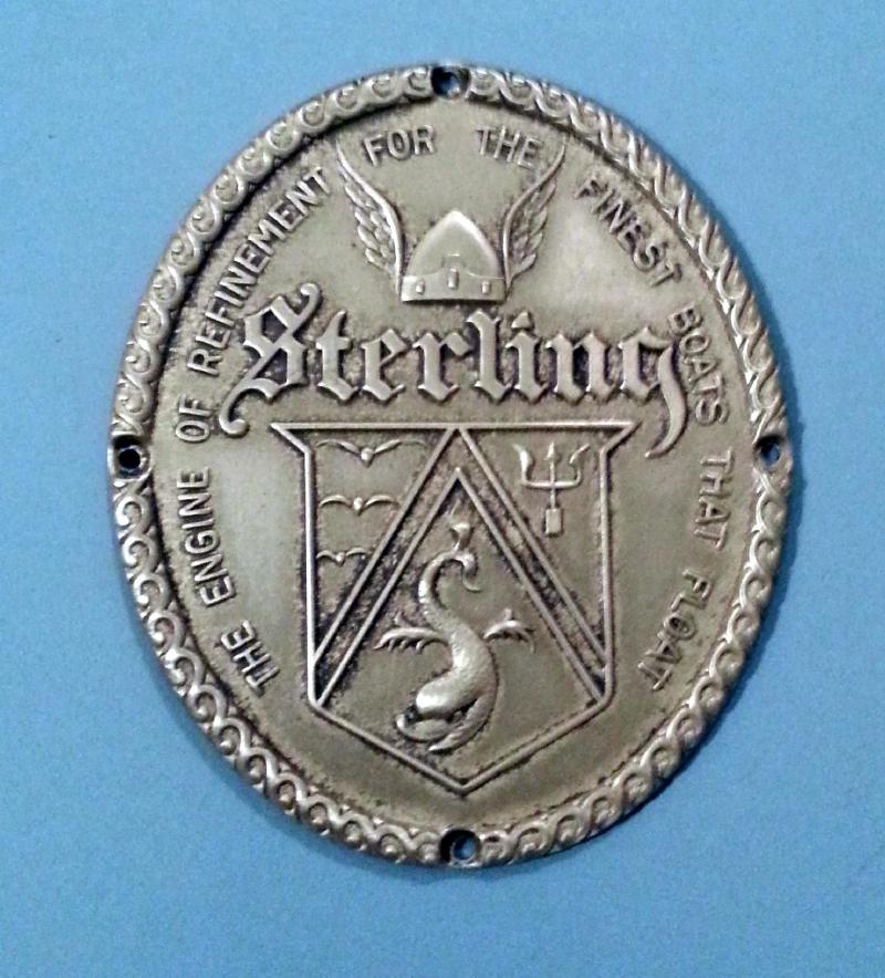
I have one of the Sterling tags like above.
I traded Bob P from NY a 6 pack of Mudd for it.
Sterling also did their tags in cloisonne
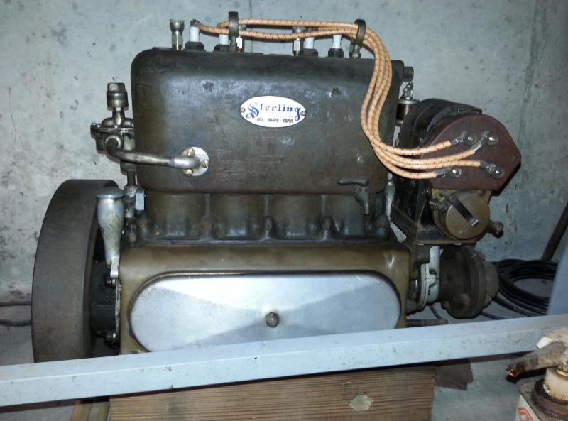
Pics of my 10 HP Model E "kid"
One of these days I will restore the engine. It does run.
 |
    
ldobbins
Senior Member
Username: ldobbins
Post Number: 154
Registered: 12-2002
| | Posted on Friday, August 29, 2014 - 12:08 pm: | 


|
Glad to see more Sterling engines showing up. I have two, one from 1906/7 and from about 1911.
Nice pic of the Kid!
Thanks,
Lew |
    
steve_hamel
Member
Username: steve_hamel
Post Number: 7
Registered: 08-2014
| | Posted on Saturday, August 30, 2014 - 01:54 pm: | 


|
With a siphon sprayer and wet vac I got the sludge out of the crankcase. Looks really good in there.
there is a wall about 4" tall separating the transmission which has no provision to drain. Tipped the engine at a steep angle and got it clean.
Found a short thin head 3/8" bolt but no sign of where it came from.
Transmission has only one over center position. Maybe the found bolt has something to do with it. I did operate the lever while cranking the engine and it functions like Lew said just no over center in reverse.
Doesn't look difficult to remove the housing so I might go in and have a look.
Got a look up the bores with a mirror and was surprised to see slipper skirt pistons. Couldn't see condition of the bores but compression is up on all four now.
'Baby steps to the bus'
Steve |
    
ldobbins
Senior Member
Username: ldobbins
Post Number: 155
Registered: 12-2002
| | Posted on Sunday, August 31, 2014 - 09:36 pm: | 


|
Hi Steve,
Your engine is a Sterling Chevron or Model C4. It looks like it was started (according to the Trade mark Office) in 1923. It was still in production as late as 1936, maybe later but was gone prior to WWII. Your engine should be rated around 90 to 100HP.
Depending upon the age, it could have had a rectangular (tall) brass ID plate on the exhaust side between the two inspection covers. Look for 4 drive screw holes. I have included a poor pic of the plate. If earlier, the ID would be an oval plate (not casting) and most likely on the front side of the cylinder above the flywheel similar to ones seen here already. I am enclosing the later style tag from an industrial version of the Chevron.
Let me know where you see holes.
Cheers,
Lew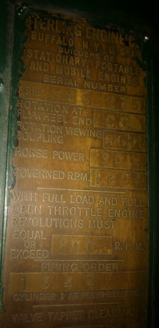 |
    
steve_hamel
Member
Username: steve_hamel
Post Number: 8
Registered: 08-2014
| | Posted on Monday, September 01, 2014 - 10:31 am: | 


|
Thanks Lew,
On my Aug. 28 post, last photo, next to the oval tag is a pattern of screw holes 2.5"x4.5". No other indications where a tag might have been.
How about a photo of the engine attached to your tag?
Steve |
    
ldobbins
Senior Member
Username: ldobbins
Post Number: 156
Registered: 12-2002
| | Posted on Friday, September 05, 2014 - 06:45 pm: | 


|
Hi Steve,
Hope you got the pictures of the Chevron Commercial I sent via email. After a little more snooping, the Chevron was gone by the end of 1938. As mentioned above, it was started in 1923 or 1924 and was still in production in 1936. So I am still up in the air as to if it was around at all in 37 or early 38.
Keep me posted on the progress.
Cheers,
Lew The West Coast Sterling Guy. |


