| Author |
Message |
    
Stephen Laskey
New member
Username: bunganucme
Post Number: 3
Registered: 08-2013
| | Posted on Thursday, August 15, 2013 - 03:58 pm: | 


|
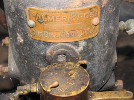
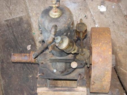
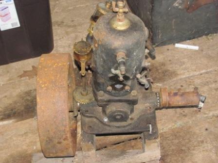
Here are some pictures of a Palmer Brothers Q 1 marine inboard engine that I have recently come into possesion of. Can any one help me identify the year this was made? Right now it's a parts engine, needing a connecting rod & a piston, among other things. Thanks for all your help.
   |
    
Ernie
Senior Member
Username: ernie
Post Number: 1705
Registered: 01-2002

| | Posted on Thursday, August 15, 2013 - 05:20 pm: | 


|
Stephen,
It appears the tag only says Q1. Since Palmer used the last 2 digits of the SN for the year of manufacture an exact year can't accuratly be determined.
However this being said
The spark plug and timer locations put it before 1912
The 2 bolt plunger type water pump puts it after 1905 but before 1916
This all being said it is most likely ca 1907ish.
I have a water pump and carb and I am quite sure someone here can come up with a piston and rod.
Mr Day do you agree?
Hope this helps
Ernie |
    
Stephen Laskey
Member
Username: bunganucme
Post Number: 4
Registered: 08-2013
| | Posted on Thursday, August 15, 2013 - 05:52 pm: | 


|
Hello Ernie. Thanks for the data. We are still looking for parts in the cellar the engine came out of, so we may find the rod, piston and other parts yet. I don't think I will be rebuilding this engine and was looking for info to use to describe the engine to potential buyers here in Midcoast Maine. Thanks again. This site has been very informative and the members more than helpful. Thanks again. |
    
Richard A. Day Jr.
Senior Member
Username: richardday
Post Number: 1073
Registered: 11-2003

| | Posted on Thursday, August 15, 2013 - 07:12 pm: | 


|
I agree with Ernie, I cannot tell but it appears the priming cup mounting in the top of the head is covering the inverted plug which Palmer used to permit boring the cylinder rather than grinding. This mounting cap appears to be brass whereas most we have seen are cast iron.
Once they switched to grinding the cylinders there was no need for that large inverted plug which permitted the boring bar to have support on the lathe tail stock. Noting there is no tag for the oil mix in the fuel I suggest we are talking about a pre1908 engine. Curious the externals of the timer are much like their "new 1912" timer. By 1916 the timer would be near the top of the head. Would like to see the internals of the timer. |
    
Stephen Laskey
Member
Username: bunganucme
Post Number: 5
Registered: 08-2013
| | Posted on Saturday, August 17, 2013 - 12:51 pm: | 


|
Richard, Attached find pics of the timer internals, FYI.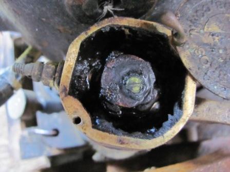 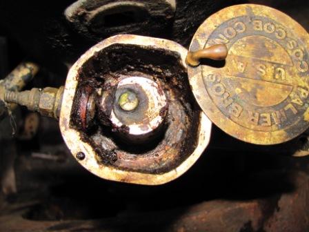 |
    
Richard A. Day Jr.
Senior Member
Username: richardday
Post Number: 1074
Registered: 11-2003

| | Posted on Saturday, August 17, 2013 - 08:23 pm: | 


|
Thanks, Stephen, Note the grease in the timer. In the old days when timers were common around the Chesapeake Bay many of the watermen kept their timers full of the same grease as used on the crankshaft grease cups. This worked very well as it kept the moisture away from the contacts and the rubbing action of the contacts made good low voltage connections. They also made friends with their local telephone company mechanics who changed out the #6 dry cell about once a year. There was often a useful life for 4 or 5 cells in a series connection. If they got weak then the watermen might punch slits in the zinc can and hang the cells over the side in salt water to in effect rejuvenate the cells. This often would get them home. Many would keep their coil and batteries at home by the kitchen stove to dry out at night. Unfortunately most of these ignition boxes would get lost when they were no longer needed as they were not kept with the boat. The ignition boxes were very carefully made with the covers arranged so water would drip off the edges and not run into the box. The wires would be arranged so water would not run down the wire into the box. Many boxes had two sets of batteries with knife switch On-OFF-On with the cells connected so one group were + to ground and the other - to ground this tended to minimize the point erosion on jump spark coils. Most coils were used Model T Ford coils as they were easy to come by and easy to trouble shoot.
One point often not understood was the practice of trouble shooting starting problems where one was not sure of the fuel mixture in the cylinders. High on the cylinder wall were petcocks which in multiple cylinder engines were connected together so operation of the Handle on on the connecting shaft would open or close all at the same time. Its purpose was to allow checking the fuel mixture in each cylinder. opening the petcock and dragging a spark wire across the petcock outlet you should get a nice blue flame. Red was too rich mixture and no flame lack of fuel in the cylinder. One can imagine the problem of trying to use a match to light the mixture in a hull bouncing around in the waves and keeping a match lighted long enough to even attempt this test.
It is unfortunate but many of these test petcocks are missing and their handle linkages are quite rare today. |
    
Paul Gray
Senior Member
Username: paulgray
Post Number: 143
Registered: 05-2003
| | Posted on Sunday, August 18, 2013 - 04:05 pm: | 


|
That is a neat trick about dunking the cells in salt water. Also liked the explanation of the petcocks. Thanks for the history lesson, Dick. |


