|
| Author |
Message |
    
rbprice
| | Posted on Sunday, October 13, 2002 - 10:35 am: | 


|
In all of the installations for old marine engines, the engine is coupled to the prop shaft with the ubiquitous double flange arrangement. And lots of advice is provided about making sure the two flanges are parallel with one another within +/- 0.003 in. or better.
In one of my old (ca 1920) MotorBoat magazines there is an advertisement for a roller chain coupling much like the ones widely available today for power transmission. Clearly, this type of coupling would dramatically reduce the need to fuss over the alignment of the two shafts since the roller chain would allow for angular, radial and axial miss-match.
Obviously, in reverse, the chain would be in tension as the prop shaft would be pulling away from the engine. And in forward, the two chain sprockets would try to come together. I'm not sure that is such a bad thing if the axial motion were less than say 0.020 in.
Anyone care to comment on why this type of coupling was not widely used?
Thanks
Bob Price |
    
richarddurgee
| | Posted on Sunday, October 13, 2002 - 03:48 pm: | 


|
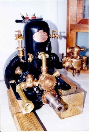
Rb : On many turn of the century engs a straight coupling was common.(Pic)To align one of these was almost an art form compared to the flat flange type. also getting these straight couplings apart was a difficult task !
The open geared waterpump like in pic also faded from the scene,as did open cam gears and lobes,and chain couplings,that attracted pant legs,ankles,fingers,rags,dirt, and general bilge debris, not to mention salt water corrosion.
 |
    
rbprice
| | Posted on Sunday, October 13, 2002 - 05:31 pm: | 


|
Great picture Richard and much of what you say is true. However, putting a guard arround a roller chain coupling is trivial compared to the fussing needed to get two flanges into alignment and keep them there. As for corrosion, the two sprockets could be made from stainless steel and for that matter so could the roller chain. Altho with a cover one could slather the coupling with open gear lube which is rather like asphalt and stays on things which rotate.
I was hoping you or someone would comment on the effects of the power impulses on the roller chain and the sprocket teeth as the reason they were not widely used.
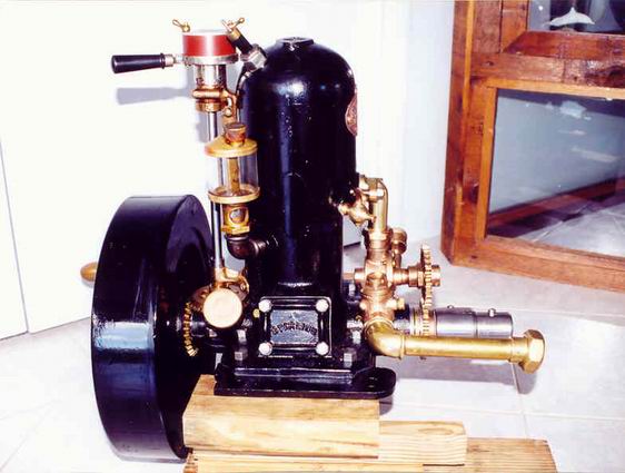
Nice engine: what kind is it and after all that work restoring it why haven't you got it on some nice finished mahogany rails? 8^)
Regards
Bob |
    
Bill Schaller
| | Posted on Sunday, October 13, 2002 - 06:45 pm: | 


|
I think it was money. 2 flanges are cheap, a roller chain coupling is expensive. The upkeep on flanges is zero. We are talking a time period where many engines did not have a magneto or transmission just to save initial cost. the labor cost of getting two flanges aligned is much lower than the chain drive. |
    
richarddurgee
| | Posted on Sunday, October 13, 2002 - 08:10 pm: | 


|
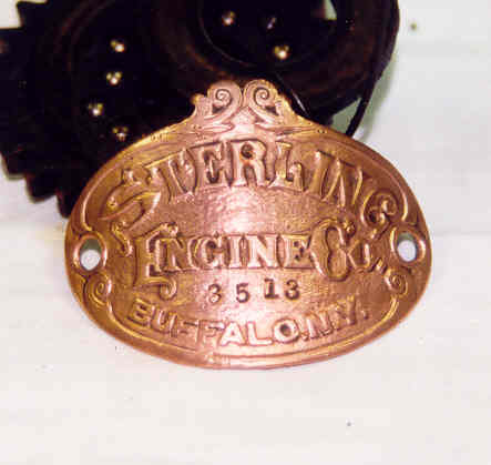
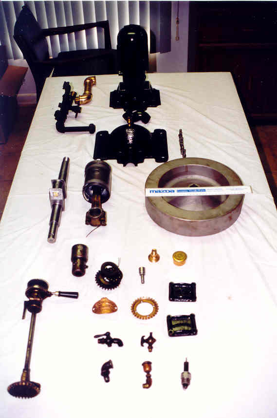
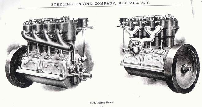
This was my first really old collectible marine engine that I found about 30 yrs ago , its circa 1906. these pics are about 15yrs old when I went through it. everything is original (except the Schebler carb, It was delivered with an "Eclipse" but I haven't been able to find one as yet)the mica plug was in it.I did find original black paint on inside of the flywheel and front eng case, so it got a coat of black eng enamel.Piston rings are pinned and look like small barrell hoops>
Does anyone know of other sterlings pre 1910 ?
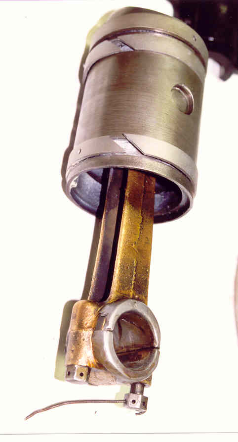 |
    
rbprice
| | Posted on Sunday, October 13, 2002 - 09:03 pm: | 


|
Good comment Bill - That rational never occured to me but it certainly has merit. Flanges require no maintenance certainly (until one tries to get them apart and the bolts are rusted tight)
And who do you know that would lay the parts to their engine out on a WHITE sheet spread out on their dining room table. Poor Mrs. Durgee. :o)
But my ultimate point about the use of a roller chain coupling is that if one were to use such a thing in a reproduction of an old wooden boat, it would be authentic.
Thanks for the commentary folks.
Bob |
    
captain Bill
| | Posted on Sunday, October 13, 2002 - 09:11 pm: | 


|
I agree with Bill Schaller Bob. A feeler gauge between the coupling flanges and an assortment of shims under the engine can make short work of the alignment problem, very inexpensive and trouble free, little to catch body parts or clothing on,no lubrication required. And what about "reversing on the spark"?, a nasty SNAP at best! In the real world however the final alignment of any coupling should be done after the hull has been "soaked" and found its true shape, this observation after having spent an hour with a dial indicator perfecting a connection on a dry hull only to go through the allignment procedure 7 days later after the hull had been in the water. Automotive type universal couplings make a lot of sense! Roller chain drives make a lot of sense. I feel if the application is period correct, go for it! |
    
captain bill
| | Posted on Sunday, October 13, 2002 - 09:53 pm: | 


|
Bob, Mrs. Durgee isn't alone , I don't use a white sheet and I bet Richard only does it for photographic purposes. Prior to assembly, marine engine parts display quite nicely on the dinning room table, candle light optional.Bill |
    
richarddurgee
| | Posted on Sunday, October 13, 2002 - 10:07 pm: | 


|
RB : Whats the mfg's name that made the chain drive, i'll try to find some info ??
The sheet is on a desk in rear office of my shop,
if that were my dining room table it would be
poor MR DURGEE !! |
    
Richard Day
| | Posted on Monday, October 14, 2002 - 08:36 am: | 


|
Interesting discussion. I use the classic three stripsof paper between the flange faces to line up the couplings. Too often the centering disk has been lost on old couplings or the available two flanges are not recessed for the same size disk and then I have had to make a replacement disk with a step down to the smaller recess. An easy but pickee job. I have two interesting Canadian drive couplings that were on Acadias. The prop end is a bronze cone about 6" in diameter with a tapered recess lined in leather. The engine end is a male tapered bronze cone that mates with the prop end. It is designed such that one starts the engine and when you want to engage the prop you grab the prop cone or push it with you boot holding it forward holding it against the engine cone. As soon as the prop begins to turn it holds the two cones engaged and off you go. To go into nuetral one reverses the two stroke and the prop pulls the cones apart and you then have to figure out if you wanted to reverse the engine after all I guess
The two cones are designed such that precise alingnment is of little consequence. I assume these couplings, clutches whatever were designed to avoid the use of a clutch with the prop haul scheme that was common in the Maritimes.
Beautiful Sterling Richard. |
    
Ernie
| | Posted on Monday, October 14, 2002 - 11:27 am: | 


|
Richard,
Where did you get the "Mazda" ruler? I have worked for Mazda for years and never seen one.
Nice engine too!
Ernie |
    
richarddurgee
| | Posted on Monday, October 14, 2002 - 06:11 pm: | 


|
This is an interesting Clutch, for use with a reversing propeller ?? 1906 ad.
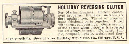
Ernie: The Mazda ruler was given out to wholesale
parts accounts from the local Delray Mazda parts dept about 15 yrs ago,if I still have it and can find it I'll send it to you ! |
    
Ernie
| | Posted on Monday, October 14, 2002 - 08:52 pm: | 


|
Richard,
Thanks but not necessary. I have so much Mazda Stuff now it would most likely get lost in the shuffle. When are you coming up north?
Thanks
Ernie |
    
Joe
| | Posted on Tuesday, October 15, 2002 - 01:16 pm: | 


|
No one has mentioned thrust bearings on this setup and I don't see any on the table. Would you put thrust bearings for forward and reverse on the prop shaft before the coupling so the engine crank doesn't take the push pull? Most of my engines are 4 cycle and have built on clutches and the thrust bearing is bolted to the engine base/frame.........As to the engine on the dining table, one day my wife said to me; "....why don't you make one of your engines into a coffee table and put it in the living room?" That was a real surprise. You gotta understand...she thinks I should collect stamps. Happy happy |
    
Richard day
| | Posted on Tuesday, October 15, 2002 - 05:12 pm: | 


|
Some reverse gears had a thrust bearing for reverse built in. The forward thrust bearing was mounted on the shaft at the aft end of the reverse gear between it and the shaft coupling. Where there was no reverse gear the forward thrust bearing would be between the coupling and the aft face of the crankcase of the engine. Reverse was handled by the aft face of the crank throw against the aft shaft bearing. In some case this was babbit and others bronze. I don't recall ever seeing a reverse thrust bearing outside or inside the crankcase in a "bob tail engine" The forward thrust bearing on the Belle Isle is inside the crankcase between the throw and the forward inside of the crankcase. |
    
Richard day
| | Posted on Tuesday, October 15, 2002 - 05:15 pm: | 


|
Some reverse gears had a thrust bearing for reverse built in. The forward thrust bearing was mounted on the shaft at the aft end of the reverse gear between it and the shaft coupling. Where there was no reverse gear the forward thrust bearing would be between the coupling and the aft face of the crankcase of the engine. Reverse was handled by the aft face of the crank throw against the aft shaft bearing. In some case this was babbit and others bronze. I don't recall ever seeing a reverse thrust bearing outside or inside the crankcase in a "bob tail engine" The forward thrust bearing on the Belle Isle is inside the crankcase between the throw and the forward inside of the crankcase. |
    
rbprice
| | Posted on Tuesday, October 15, 2002 - 09:19 pm: | 


|
Well now folks - the presumption is that the engine or gearbox has the thrust brgs. built in.
For instance, my Ferro's and my Cady have the thrust brg. built into the rear of the crankcase in the form of two hardened plates with ball races in the face of the plates and the balls in a brass ring with holes holding the balls. I suspect that is/was typical of many early engines.
The issue of axial play and the radial shock upon reverse of a two cycle engine may have been a factor in the lack of use of the roller chain coupling (as well as the cost factor). But Captain Bill verifies my comment about the time to do a proper alignment and the fact that numerous factors can change that alignment. The old boatmen did not, I suspect, check the alignment very often, if at all, unless there was a loud thumping or loss of power indicating a problem. A roller chain coupling would have significantly mitigated that problem.
I want to try this idea with a Stuart-Turner in a small, 16 ft., boat and the S-T has a gearbox so I won't (hopefully) be plug reversing.
And of course, if the thing destroys itself, I can always intall two flanges. 8^)
Bob |
    
Joe
| | Posted on Wednesday, October 16, 2002 - 01:13 am: | 


|
Yo Bob....so if you have a chain coupling the engine to the shaft and you run the engine in reverse, will the chain coupling be taking the reverse thrust? Would you not put a reverse thrust bearing on the shaft steady bearing which would probably be just behind the chain coupler
If the chain let go in reverse it could get messy.......Mo from Joe |
    
George Coates
| | Posted on Wednesday, October 16, 2002 - 04:50 pm: | 


|
My early Gray Motor Co has a ball thrust bearing on the crankshaft between the rear throw and inside the rear case for reverse. Forward thrust is taken by a ball bearing between the flange and the case on the outside. The "newer" Grays have forward ball bearing thrust only. |
    
olarry
| | Posted on Wednesday, October 16, 2002 - 07:11 pm: | 


|
I have 10 tractors with chain couplers between the clutch shaft and transmission,they turn up to 2400rpm.If you want to keep them on the thing to do is use a long cotter pin that goes through both pins of the master link.This stops the pins from rotating and stops lots of wear on the pins and cotter pins.One set I have has no master link,it is held on by an outer sleeve that you just slide overtop.It only turns about 500rpm. |
    
rbprice
| | Posted on Wednesday, October 16, 2002 - 08:46 pm: | 


|
My 1905 Ferro has the rear hub pinned to the shaft with a large set screw that fits into a recess on the end of the crank shaft. The thrust brg. is sandwiched between that hub and the rear of the crankcase. So in forward, the axial thrust from the prop goes into the end of the crankshaft, into the hub thru the large set screw and presses on the races of the thrust brg. That axial load in taken by the crankcase.
In reverse the axial pull is taken by the cheek of the throw on the crankshaft inside the crankcase and is lubricated by the grease from the rear bearing. Since the engine did not spend much time in reverse that was adequate.
As for Olarry's high RPM tractor, high RPM equals relatively low torque [unless your foot slips off the clutch :0( ] But the idea of a long cotter pin thru the ends of the master link is a good one. |
    
richarddurgee
| | Posted on Sunday, October 20, 2002 - 11:50 am: | 


|
RB: This 1908 A.A.Adams Marine engine(Providence R.I.) seems to have a chain coupling drive, it appears to drive the prop via an offset auxilliary shaft that would put no fore and aft loads on the engs crankshaft. I'd like to read the book on installing and aligning this set up ???
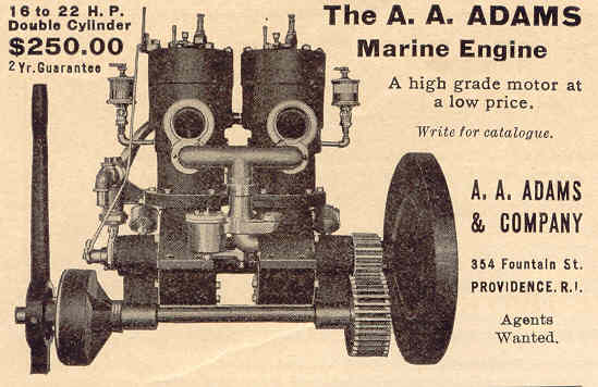
Ernie: Thanks for STERLING pic, early small sterlings seem to be a rarity?? |
    
richarddurgee
| | Posted on Friday, October 25, 2002 - 08:40 pm: | 


|
R.B. Price
Finally found the chain coupling ! 1916 publication.
 |
    
ldobbins
New member
Username: ldobbins
Post Number: 5
Registered: 12-2002
| | Posted on Thursday, August 26, 2004 - 05:27 pm: | 


|
Hi Richard,
Just going through some back listings and came across your little Sterling. Beautiful!! Have you been able to date this engine by the sn (3513)? Or do you know if there is more to the number than just a Serial Number?
You were asking about other pre 1910 Sterlings: I have a 12-15 HP four stroke, 4 cyl estemated to be 1907.
Cheers,
Lew |
    
richarddurgee
Senior Member
Username: richarddurgee
Post Number: 536
Registered: 11-2001

| | Posted on Thursday, August 26, 2004 - 06:44 pm: | 


|
Lew Thanks it's one of my favorites, not enough of them around to have figured out the serial No's.
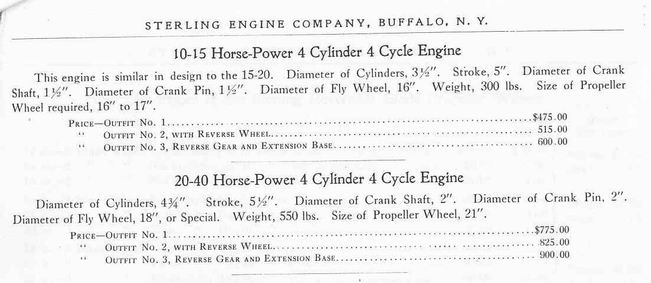
Sterling started making two stroke marine engs in 1902 and they had cylinder heads, in 1906 the 2 1/2 hp and up were headless, this one i believe is one of those early ones (2 1/2hp).
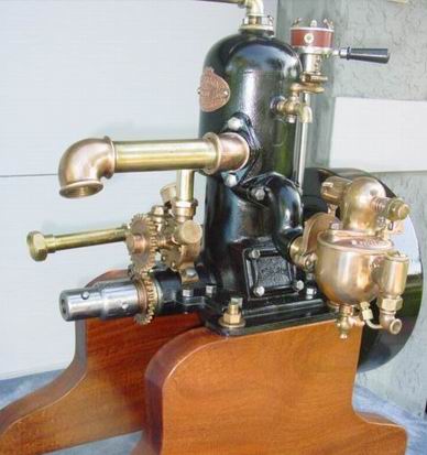
This is from Sterlings 1907 catalog.
Lew possible to e-mail photos of your engine to me? I'll post them on this site, would like to see it! [email protected]
 |
    
poker casino155
Visitor
| | Posted on Monday, March 06, 2006 - 04:24 pm: | 


|
poker casino poker 484 |
    
Ned L
Visitor
| | Posted on Friday, January 16, 2009 - 01:19 pm: | 


|
Chain couplings are still in common use in inboard raceboats as it allows for changing allignmet as the hull flexes. |
    
Cheyenne C.
New member
Username: xoecraft
Post Number: 1
Registered: 07-2009
| | Posted on Wednesday, July 29, 2009 - 04:14 pm: | 


|
Who is currently making Chain couplers ? and are any of them for higher RPM ? say 5-6000 ? |
    
Frank Petran
Senior Member
Username: frank_petran
Post Number: 56
Registered: 05-2009
| | Posted on Wednesday, July 29, 2009 - 05:16 pm: | 


|
Dodge or Falk and a few others still make Chain Couplers. Most any power and transmission supply house can steer you in the right direction. The case for flange couplers. First this is the best system for proper alignment of the engine and propshaft. Second, A lot less metal going around and around with things like links moving around and creating an impabalance in the system. Third, if it is so great the people like Chris-Craft, Burger Boats, SeaRay and many more than I wish to count would be using them. The idea of an U joint is really not something a sane person would do. Shaft failure prior to the stuffing box would cause much damage if not injuring someone(A rotating snake). Leaves to much room for poor insulation of the propshaft and engine. Lots of room for errors. If the boat has so much rocker or hog to it, it is time to repair it. Ihave been around boats for over 50 years, mainly wood ones and I haven't seen one chain coupling or U joint boat that wasn't in need of major keel, keelson damage because the misalignment usually end up damaging something else, the strut takes the forces and pulls on the fastners in an effort to stay aligned as the prop shaft, strut cutlas bearing try to maintain the proper clearances. |
|
|
|


|


