| Author |
Message |
    
barry
Member
Username: barry
Post Number: 5
Registered: 02-2006
| | Posted on Tuesday, July 25, 2006 - 01:13 pm: | 


|
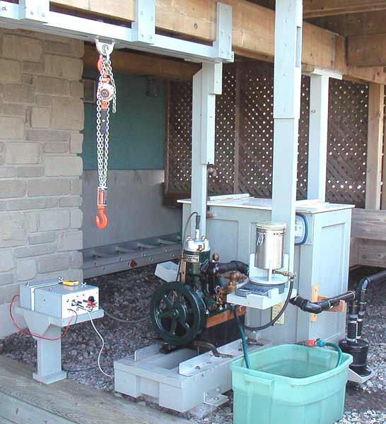
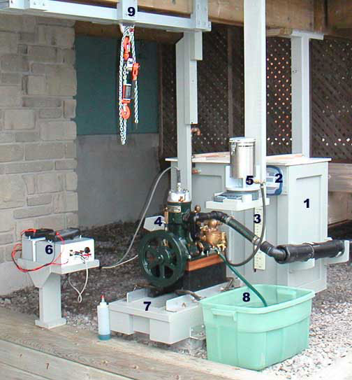
Attached is an image of an engine test bench, used for performance evaluation of small one and two cylinder two cycle marine engines,
An engine is operated against a load that can with precision be easily and quickly changed. Another important feature is the physical arrangement. The test bench is installed at a comfortable height so that adjustments are easy to carry out compared to the same engine installed in a boat.
This bench uses digital instrumentation to measure key operating parameters. HP, torque, fuel consumption, operation stability, fuel use efficiency etc can be quickly calculated. Therefore small changes can be evaluated. The goal is to determine conditions that result in maximum output and to better understand the theory and fine points of two cycle marine engines.
Barry Millar
 |
    
keith
Senior Member
Username: keith
Post Number: 130
Registered: 02-2002

| | Posted on Tuesday, July 25, 2006 - 01:55 pm: | 


|
Barry
That is a great setup. Is it something you designed yourself? Is this a hobby, or part of a business? If it is a business, what type? The answer to these questions will lead to more questions.
Keith |
    
jb_castagnos
Senior Member
Username: jb_castagnos
Post Number: 154
Registered: 07-2002
| | Posted on Tuesday, July 25, 2006 - 07:53 pm: | 


|
Barry, I've been wanting something like this, doubt if I'll ever get time to make it, looks great. What do you use to load the engine, I was thinking a hydraulic pump. |
    
richardday
Senior Member
Username: richardday
Post Number: 364
Registered: 11-2003

| | Posted on Tuesday, July 25, 2006 - 09:30 pm: | 


|
Nice job.Barry. Do I gather you have a prop in the tank which circulates the water providing a load? |
    
barry
Member
Username: barry
Post Number: 6
Registered: 02-2006
| | Posted on Wednesday, July 26, 2006 - 06:53 am: | 


|
Keith,
I designed and built the test bench in 2005 for my own use as a hobby.
Regarding interest in the method used for loading the engine under test, I will locate some images and post these later.
Barry |
    
barry
Member
Username: barry
Post Number: 7
Registered: 02-2006
| | Posted on Wednesday, July 26, 2006 - 03:59 pm: | 


|
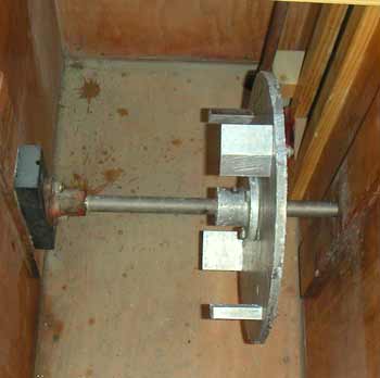
When an engine propels a boat, engine RPM is limited by the diameter and pitch of the propeller. A load wheel rotating in a tank of water simulates a propeller, however all the energy available to propel a boat instead causes an increase in water temperature.
One image illustrates the load wheel. It is a 1/2" thick aluminum plate, 12 inches diameter. Four paddles are attached to the plate using a single stainless steel screw and locknut. Leading edge of each paddle is chamfered to reduce vibration. Paddle angle is set by loosening, adjusting, and then tightening each nut in turn. Wheel is keyed to a stainless steel shaft that is supported by a stuffing box attached to the outside of the box and a bronze bearing fastened to the inside of the box.
Water box is 15" x 30". Inside surface is epoxy coated. Water level is always maintained above the shaft to ensure bearing cooling and lubrication. Paddle angle is first set to establish a load range, then water level is adjusted to fine tune engine load.
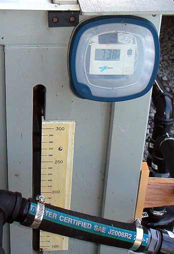
The second image shows a digital thermometer that measures water temperature in degrees Fahrenheit. The vertical scale displays quantity of water in the box, in pounds.
One BTU is the energy required to raise the temperature of one pound of water, one degree F. If for example, during a typical six minute test, the water box contains 200 pounds of water and the temperature increases 3 degrees F then the energy transferred by the engine to the water is 200x 3 = 600 BTU. This is equivalent to 6000 BTU per hour since test duration is 1/10 hours.
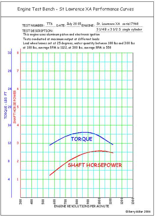
One horsepower is equivalent to 2544 BTU per hour. Therefore these example test results show that the engine was operating at 2.4 HP. This is "shaft horsepower, the HP available to propel a boat. The engine under test is a two cycle machine that displaces 29 cubic inches and develops 2.4 HP. Maximum HP occurs when loaded to about 900 RPM. Maximum torque occurs when loaded to about 840 RPM.
This test method makes it possible to compare engine performance over a range of engine settings and adjustments.
Barry
 |
    
solarrog
Senior Member
Username: solarrog
Post Number: 166
Registered: 03-2002

| | Posted on Wednesday, July 26, 2006 - 04:06 pm: | 


|
Wow, Now my head hurts
You can sure tell im not an engineer |
    
keith
Senior Member
Username: keith
Post Number: 131
Registered: 02-2002

| | Posted on Wednesday, July 26, 2006 - 04:36 pm: | 


|
Neat Barry,
When starting with a new motor, one in which you don't know the HP or RPM required for the most HP, what are the steps you take to develop this data? How do you determine the RPM for the highest torque?
Keith |
    
barry
Member
Username: barry
Post Number: 8
Registered: 02-2006
| | Posted on Thursday, July 27, 2006 - 12:17 pm: | 


|
Keith,
Answering your question .... I conduct about 5, six minute tests with engine operating at maximum RPM during each test. I change load for each test so that the resultant engine speed covers what I feel is a useful range for the particular engine, using an experience based guess.
In addition to the data listed in my previous post, I also record average RPM for each test so that torque can be calculated.
I then plot HP and Torque against RPM to identify engine speed that results in maximum HP and maximum torque. I prefer to size a propeller to load an old two cycle engine for maximum torque rather than maximum HP.
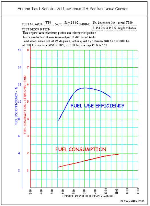
I also collect fuel consumption information and plot a fuel consumption curve and a fuel use efficiency curve. The best fuel use efficiency is about 13%, meaning that only 13% of the energy contained in the fuel is available to propel a boat.
When it interests me, I also record the energy lost in cooling water.
My principal objective is to attempt to better understand and quantify a long list of mysteries and folklore associated with old two cycle engines. I suspect this will keep me occupied for some time.
I wonder whether others are like minded.
Barry |
    
robert
Senior Member
Username: robert
Post Number: 115
Registered: 07-2003
| | Posted on Sunday, July 30, 2006 - 03:58 pm: | 


|
Superb!
How do you prevent heat loss through the walls of the box? I don't see any insulation? |
    
barry
Member
Username: barry
Post Number: 9
Registered: 02-2006
| | Posted on Monday, July 31, 2006 - 05:01 pm: | 


|
Robert,
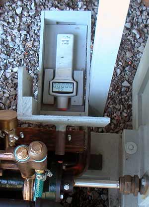
I appreciate and welcome your interest. I wonder if any one may wish to consider building a similar set-up, maybe without all the instrumentation, just make it convenient to install different engines and run them against an easy to adjust load. Will be pleased to provide information about my installation with sketches if need be. A digital tachometer is very useful. I'll attach an image of the unit that I use. It is used to monitor various engine adjustments, usually to establish maximum RPM. It is highly sensitive to carburetor fuel adjustment, air valve adjustment,ignition setting etc.
This is an optical tachometer. A small piece of reflective tape is attached to the engine coupling. The tachometer accurately measures the time between reflective pulses of light, calculates RPM,then displays RPM as a digital readout.
Stability of rotational speed can also be measured and displayed on the digital readout.
Average: the average RPM during the test period
Maximum: the peak RPM that occurred during the test period
Minimum: the least RPM that occurred during the test period
The tachometer can also be used to count pulses. This provides a high accuracy measurement of engine stability as the exact number of revolutions can be recorded over an exact test period.
Regarding your question, I decided not to bother insulating the box so maybe the HP is slightly understated. As the temperature rise of the water is only a few degrees above ambient I thought there would be very little heat loss to atmosphere. Additionally the usual test time is about 6 minutes and again because of the small temperature difference and because the box is built from wood which is a poor conductor, there should be little affect on the result. The load wheel is aluminium which is a good conductor so heat caused by friction between the wheel and surrounding water is transferred rapidly to the water.
If it will be of interest, I'll try to post some typical performance curves.
Barry
 |
    
robert
Senior Member
Username: robert
Post Number: 116
Registered: 07-2003
| | Posted on Monday, July 31, 2006 - 07:21 pm: | 


|
Quite fascinating. If you wouldn't be revealing more than you wish, what are some of those mysteries associated with early two cycle engines?
Thank you for sharing this with us.
I can't help wondering what effect the condition of the various engines may have on the test results, considering their age.
Though probably we can assume that your restorations are equally meticulous and your engines therefore as close to new as they can be made!? |
    
joe_h
Member
Username: joe_h
Post Number: 7
Registered: 05-2005
| | Posted on Saturday, August 05, 2006 - 01:43 pm: | 


|
Hi Barry...I faintly recall a study done by university students to determine the true HP of early engines. Was this you? Their interest was to compare engine builder's stated horsepower to actual horsepower. The builders determined HP mathematically using as I recall, bore stroke rpm some constant and etc. The study found that builder's calculated HP was understated. I would tend to believe the dyno method, which is what you have, as more accurate. It would be interesting to try this out......can you make your unit mobile? (kidding) I expect there are many of us that have engines we would like to tune and measure. Some of the engines I have list their HP as a range such as 4-6, 7-9, 10-14 etc. I am not sure if the manufacturer was covering all bases or the HP range refered to what RPM was turning. I bet you would know. Nice going........Joe |
    
barry
Member
Username: barry
Post Number: 10
Registered: 02-2006
| | Posted on Saturday, August 05, 2006 - 04:12 pm: | 


|
Am attaching performance curves for the one cylinder two-cycle engine shown in my July 25 post. Will appreciate comments regarding interpreting these data.
Barry
 |
    
barry
Member
Username: barry
Post Number: 16
Registered: 02-2006
| | Posted on Saturday, September 23, 2006 - 01:55 pm: | 


|
I mentioned in one of my prior posts that I use my test bench to attempt to understand the mysteries of 2-cycle marine engine operation.
Here are results of an investigation intended to establish best settings for the Schebler Model D compensating air valve. The result, rather than providing clarity, added to the mystery.
Recall the test engine is a 3 port St Lawrence one cylinder with Schebler Model D carburetor. It uses my electronic timer in combination with a buzz coil, so timer related ignition faults during the tests were eliminated. Two 30 minute tests were conducted. Prior to each test, the crankcase was drained and sponged clean. At the end of each test, the content of the crankcase was collected and measured.
Test one:
Test tank water level set to limit engine RPM at maximum torque. (refer to graphs attached to August 05 post)
Carburetor throttle plate full open, ignition advanced and carburetor needle set for maximum RPM.
Air valve spring force gradually increased so that maximum RPM was slightly reduced and controlled by the air valve setting.
Results:
HP 2.27
Average RPM 850
Fuel used 661 grams (.88 litres, .26 US gals)
Crankcase contents after test - 20 milliliters
Exhaust color – very slight gray
Test two:
All condition same as test one, except compensating air valve and spring were removed.
Results:
HP 2.34
Average RPM 860
Fuel used 615 grams (.82 litres, .22USgals)
Crankcase contents after test -15 millilitres
Exhaust colour – very slight gray
These tests results suggest engine operation is more efficient with air valve removed - significant less fuel used, bit more HP, 25% less crankcase build-up. I was perplexed with this result so I operated the engine over a full range of speeds from idle to maximum and found the operation the same with or without the air valve.
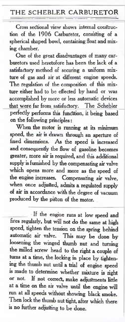
Wheeler & Schebler published a little booklet about 1908. Included is information about the Compensating Air valve. Excerpts from this booklet are attached. This information published about 1906 seems to conflict with my 2006 test results !!!!
I will much appreciative receiving comments of others so as to help get me back on a path to understanding this mystery.
 |
    
george_iv
Senior Member
Username: george_iv
Post Number: 51
Registered: 07-2003

| | Posted on Saturday, September 23, 2006 - 08:46 pm: | 


|
I'm impressed with your test stand and testing work with these engines! I believe that the air valve is a high speed enrichment device and may be not needed on the relatively small St. Lawrence with the size carb used. Is it possible in the first test that the setting caused just a tad rich running because of the extra restriction of the air valve? I'm happy when I can get an engine to run without the Schebler leaking on everything!
George |
    
richarddurgee
Senior Member
Username: richarddurgee
Post Number: 1225
Registered: 11-2001

| | Posted on Sunday, September 24, 2006 - 12:47 am: | 


|
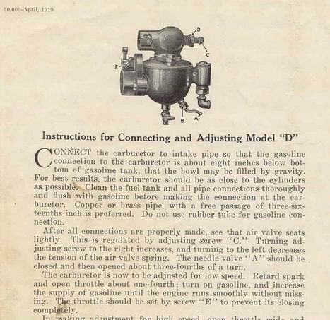
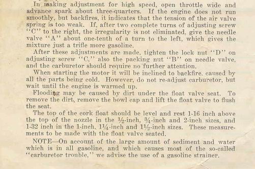
This is the only factory instructions for Model D that I have ! 1919
 |
    
ernie
Senior Member
Username: ernie
Post Number: 457
Registered: 01-2002

| | Posted on Sunday, September 24, 2006 - 08:42 am: | 


|
The instructions posted above by Richard are correct.
To paraphrase them:
The needle valve is for low speed
The air valve is for high speed (throttle open more than the little bypass around the air valve)
The float valve settings are way to high for a show engine. If you are only running an engine for show out of a boat set the float as low as possible.
By the way Richard these are the best Schlebler instructions yet. Thanks for posting them
By the way Andrew, can you add Richards instructions the the Schlebler page please.
This is one of the things that was the subject of another post a few weeks ago about threads going off topic. This is good carb info that will be hard to find in a few days or weeks. The info is good here, but needs to be where it can easily found.
Thanks
Ernie |
    
barry
Member
Username: barry
Post Number: 17
Registered: 02-2006
| | Posted on Sunday, September 24, 2006 - 03:43 pm: | 


|
George,
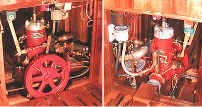
Your comments are very helpful. My interest pertains to understanding the fine points of old two-cycle engine operation and this subject is a good fit. I use an engine identical to the test bench engine to power my boat so am able to validate test bench discoveries in real life. (image attached)
The Schebler instructions, both the 1919 version and the 1908 version explain the purpose of the compensating air valve as a device to control air supply volume as engine speed increases, when the by pass is not longer adequate. During test one, the compensating air valve was functioning as intended. I had previously glued a small stick to the valve so that the stick extended outside the horn in order to better understand its operation.
The mystery relates to engine operation during test two when the air valve was removed. The engine operated smoothly from idle to maximum. This is a challenge to understand and to be able to explain.
The lower fuel consumption during test two also requires further study. It is possible as you suggested that the needle valve was set a bit rich during test one and even though it was not changed for test two the result was a leaner mix and corresponding less fuel used. I intend to conduct another test to try to confirm and better understand this.
To add more information to the melee, I am also investigating fuel spray nozzle characteristics. I measured several carburetor needle angles at 40 degrees so I made up needles at 35, 30 and 25 degrees to study spray pattern and corresponding engine operation. To observe spray pattern, I remove the air horn. Thus the spray nozzle is visible. To keep the engine operating, it is necessary that I use my thumb to reduce airflow. However when the air horn (without the air valve) is replaced, engine operates without using my thumb to reduce airflow. Any thoughts ??
All this contributes to a larger area of understanding. A very spirited and powerful discussion occurred last winter that started with a post by John Drabik on Jan 20 regarding two-port check valve. The information in this post relative to carburetor operation is applicable to my current test bench program. http://www.oldmarineengine.com/discus/messages/1/10249.html
Incidentally, George, you mentioned,
“I'm happy when I can get an engine to run without the Schebler leaking on everything!”
Could you provide more information regarding this leaking.
Barry
 |
    
barry
Member
Username: barry
Post Number: 18
Registered: 02-2006
| | Posted on Sunday, September 24, 2006 - 03:44 pm: | 


|
Ernie,
Regarding float valve setting, I conducted a brief test.
When the test engine was operating under maximum load, I turned off fuel supply and recorded RPM at 5 second intervals until the engine stopped.
Engine speed remained constant at 840 RPM, +/- 2 RPM for 2 1/2 minutes then fell rapidly to zero during a final 5 seconds.
Barry |
    
ernie
Senior Member
Username: ernie
Post Number: 458
Registered: 01-2002

| | Posted on Monday, September 25, 2006 - 08:25 am: | 


|
Barry,
The float level is related to fuel sloshing. On an engine running with no load and not bolted to anything the only way I have found to keep fuel mixture constant is by setting the float as low as possible.
Your mini dyno has the engine bolted solid and running with a load just like in a boat. |
    
bcm
Member
Username: bcm
Post Number: 21
Registered: 11-2009
| | Posted on Friday, July 01, 2011 - 02:23 pm: | 


|
I’m finished using this test bench, having explored many fine points of 2 cycle marine engine operation, thus plan to dismantle the bench and use the parts for other applications.
It occurred to me that some collector may wish to acquire the bench as it is fully operational and is a very convenient system to operate and evaluate small marine engines. I’ll delay dismantling the bench until August to provide an opportunity to explore this possibility.
Suggest if interested, read this thread from the beginning then contact me by email to engage in conversation and agree on price for those components of interest, just click on my username to access my email address. The bench also includes all the parts to adapt an engine to an electronic timer as discussed elsewhere at …..
http://www.oldmarineengine.com/discus/messages/3457/96400.html
It‘s convenient to pick up the bench in Port Colborne as it is not easily shipped. Port Colborne is in Canada less than one hour drive from Buffalo. I would keep the bench intact so as to be able to be able to set it up and operate it for a new owner.
I have used the bench to operate and evaluate St Lawrence two stoke engines from 3 to 8 HP. Minor modification would facilitate operating other engines within this HP range.
Barry
 |


