| Author |
Message |
    
[email protected]
New member
Username: fordsonguy
Post Number: 1
Registered: 01-2008
| | Posted on Monday, January 14, 2008 - 07:25 pm: | 


|
I HAVE FOUND A PALMER ENGINE THAT I CAN FIND NO INFORMATION ON. THE SERIAL # IS Q2 1072416 IT APPEARS TO BE A TWO STROKE TWO CYLINER INBOARD ENGINE. IF YOU COULD GIVE ANY INFORMATION OR WHERE TO FIND INFORMATION I WOULD BE GREATFUL THANK YOU
JASON |
    
Robert
Senior Member
Username: robert
Post Number: 199
Registered: 07-2003
| | Posted on Tuesday, January 15, 2008 - 02:15 am: | 


|
And still they turn up!
Dick will be along any minute now...! |
    
Richard A. Day Jr.
Senior Member
Username: richardday
Post Number: 554
Registered: 11-2003

| | Posted on Tuesday, January 15, 2008 - 09:07 pm: | 


|
Andrew sells reprint copies of the 1907 Palmer Bros. catalog which the Q-2 is shown on pages 12,13 and 14. It is 4 hsp at 550 RPM weighs about 245 lbs and was made in 1916 according to your serial number. I would be interested to know if the water pump flange bolted to the aft cylinder has a two bolt flange or a three bolt flange. I would expect it to be a three bolt but not enough in the years 1914 to 1917 have turned up to know when they made that change. They are very desirable engines and run very well. Andrew also sells the Palmer Handbook Reprint you will find very useful in getting it running. I collect Palmer serial numbers and am always looking for photos of engines with serial number to be posted on here as they help all of those collecting Palmers in identifing when changes took place over the production years. We now know they used the last two digits of the serial number as the year the engine was made. The earliest number that follows that pattern is 050809 1909. What or how they identified their earlier engines we don't have enough data to say. I would like to add your engine to the 2007 listing which I hope to have in the mail by Mar. I don't put the names and addresses of the owners etc on the internet as there are too many people mining the internet for who knows what purpose. In my mailing it only goes to owners and marine museums and there is no charge. You are welcome to contact anyone on the list as far as I am concerned as that is what it is intended for. No one to date has violated my request and I hope it stays that way. If you want to be added to the listing please send me an e-mail with name address telphone etc. Hope this helps. |
    
JASON O'BRIEN
New member
Username: fordsonguy
Post Number: 2
Registered: 01-2008
| | Posted on Thursday, January 17, 2008 - 09:55 pm: | 


|
Hi, thankyou for the information, the engine has the three boult pattern you though! I would like to be on the mailing list my address, Jason O'Brien 76 Packer RD. Canterbury Ct. 06331 I would also be interested in trading this engine for a hit @ miss farm engine because that's were my primary intrests are. please feel free to call me evenings at 1 (860) 546 9803 Again very greatful for your time. Jason O'Brien |
    
Searcher
Senior Member
Username: searcher
Post Number: 331
Registered: 10-2004
| | Posted on Tuesday, September 08, 2009 - 12:56 am: | 


|
Dick,
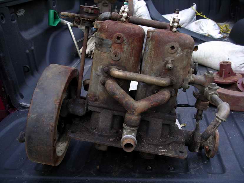
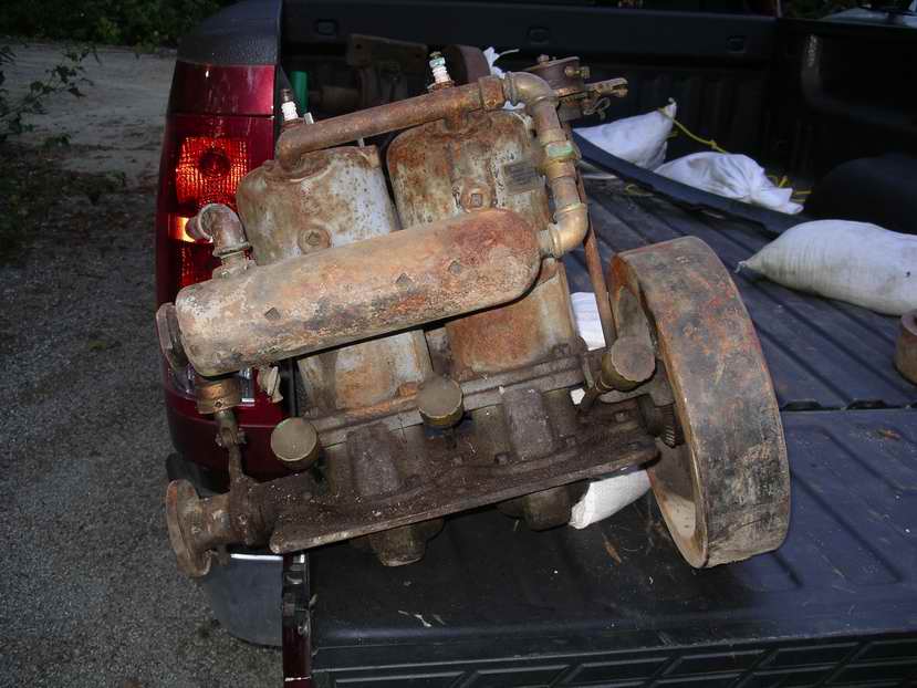
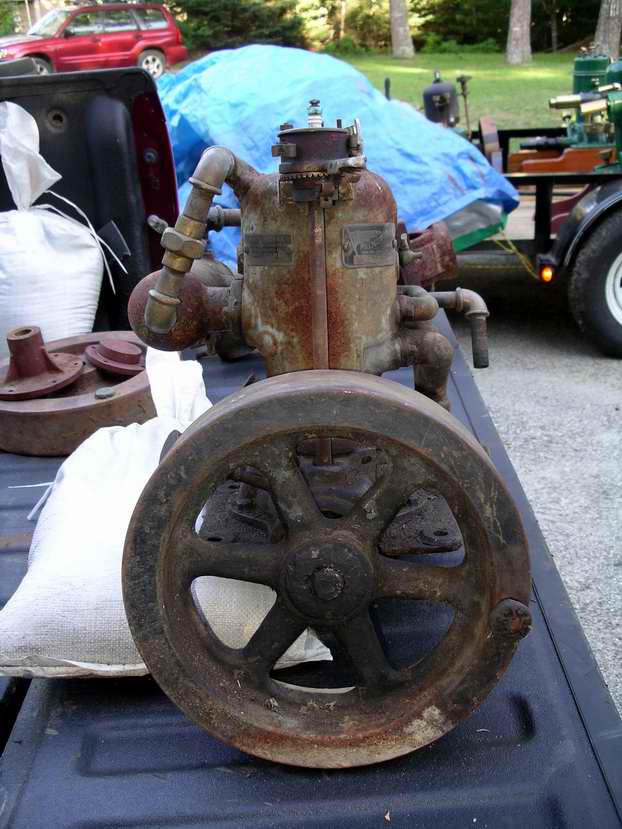
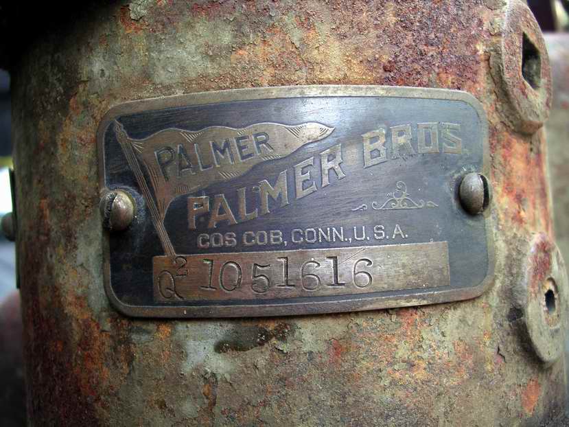
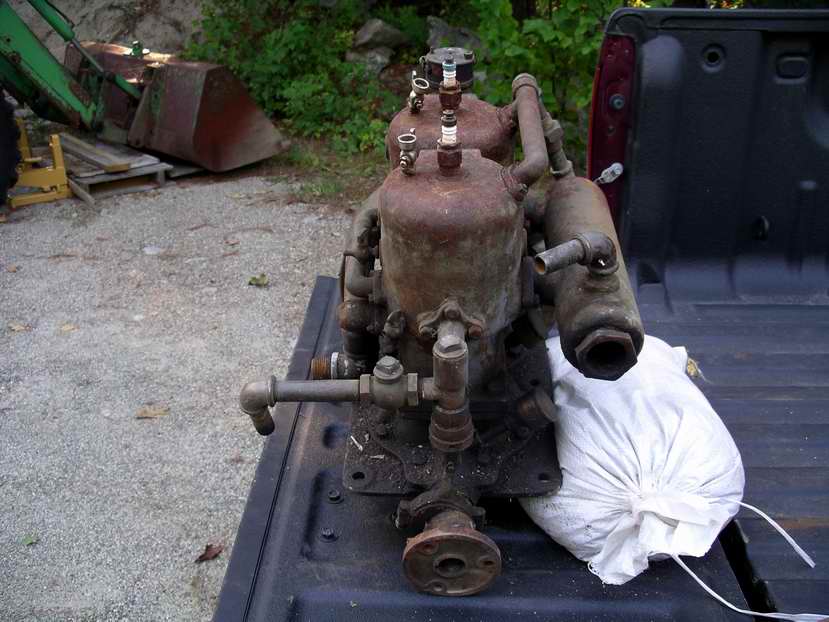
Here is another Q2 for your list. What did these have for the original carburetor?
 |
    
RichardDurgee
Senior Member
Username: richarddurgee
Post Number: 2166
Registered: 11-2001
| | Posted on Tuesday, September 08, 2009 - 09:16 am: | 


|
*
Nice to find them original and complete like this one !
OE Carburetor was Schebler D
** |
    
Richard A. Day Jr.
Senior Member
Username: richardday
Post Number: 800
Registered: 11-2003

| | Posted on Tuesday, September 08, 2009 - 11:36 am: | 


|
Palmer early catalogs make the point they Prefer Schebler Model D Carburetors but they would supply any of the contemporary knock off if the buyer specified. To me that means Monarch, Michigan Wheel, Generator Valve etc. I expect Kingston, Krice etc. were also acceptable you name it.
They also make the statement in the case of their models C,D and E they would only rate them with the Schebler model D.
This engine is remarkably complete Note the gear guard is still in place. Often this is missing and the two mounting cap screws are missing which results in the crankcase is exposed to atmosphere as the screw threads penetrate the casting. In the single this would make for difficult starting thats for sure.
The oil mix tag and serial number tag fortunately are not missing. The water pump flange on the early O,P and Q models have a two bolt flange I have a 1916 wih the same 3 bolt flange as this engine. I have not been able to resolve when the change from two to three bolt flanges took place. Knowing the approx date would permit narrowing down production years for particular engines missing their serial number tag.
It seems the introduction of the OIL MIX tag must have begun in late 1910 or early 1911.
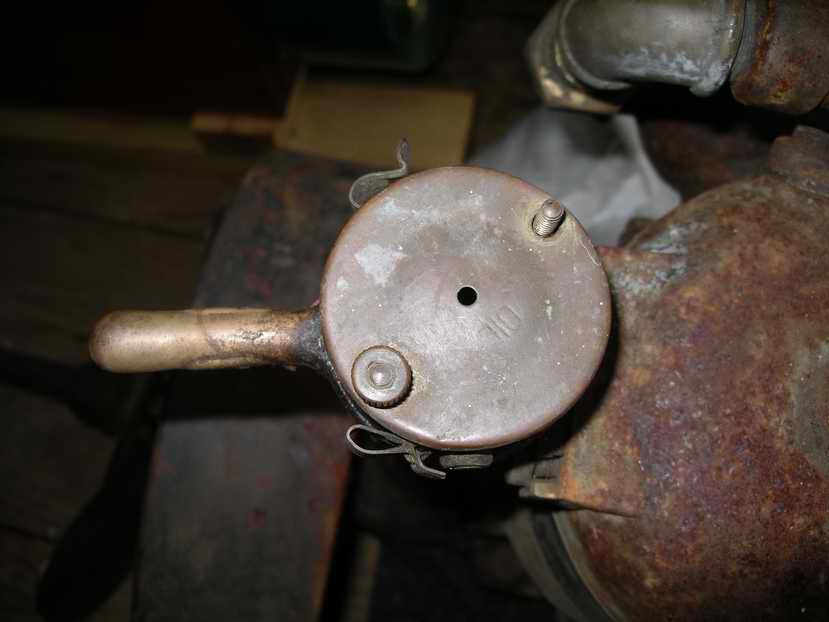
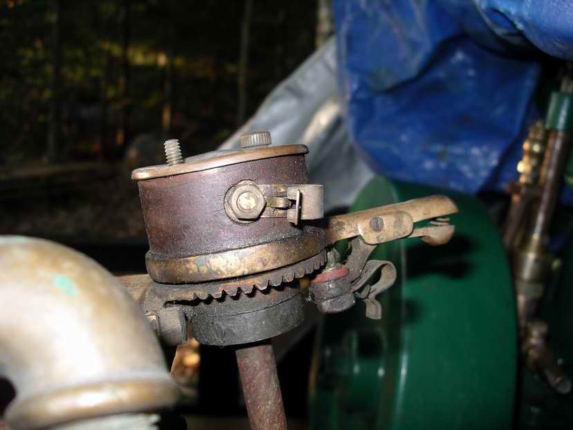
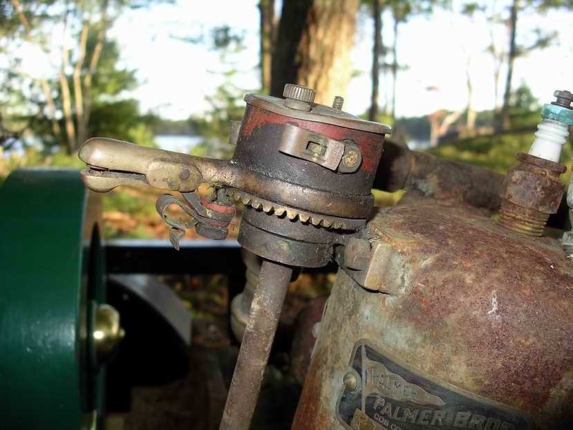
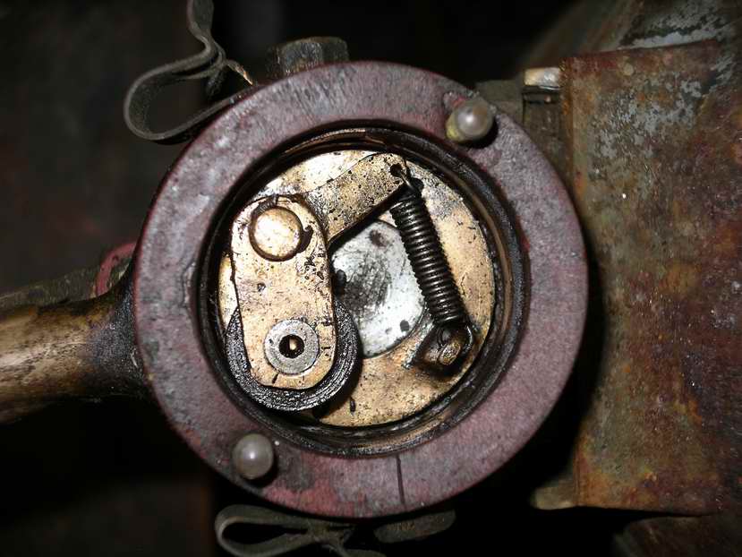
This engine has an original Palmer timer. What model timer I cannot tell. It appears to be much like the 1912 timer. Would be helpful if I could get a photo or two of the timer for my records.
The brass "pant cuff protector" is missing from the hub of the flywheel. It was typically held in place with a 10/32 machine screw. The face of the flywheel hub is recessed to hold the brass cap centered in place. The broken petcock on the Port cylinder wall was intended to allow one to determine the color of the mixture when burning. Curious the nickel plated petcocks are not also brass. Thanks for the great photos. |
    
RichardDurgee
Senior Member
Username: richarddurgee
Post Number: 2167
Registered: 11-2001
| | Posted on Tuesday, September 08, 2009 - 01:53 pm: | 


|
*
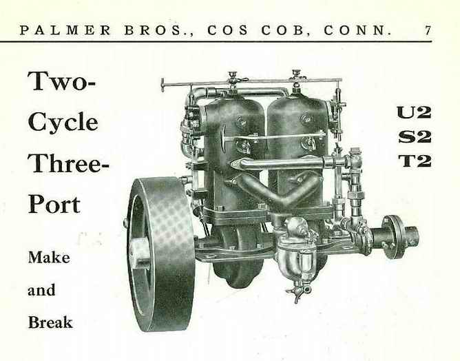
Palmer U2 1913
Palmer Q2 1913
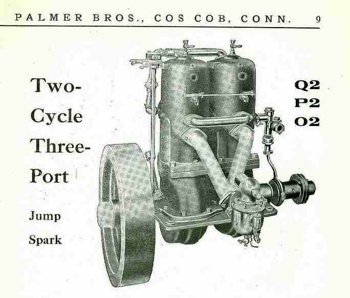
By 1916 the Q2 engine above has similar traits to the 1913 U2 in ?
** |
    
Richard A. Day Jr.
Senior Member
Username: richardday
Post Number: 801
Registered: 11-2003

| | Posted on Tuesday, September 08, 2009 - 04:54 pm: | 


|
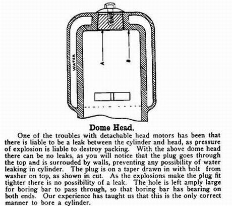
Richard, There were two version of the engines called the Models O, P and Q These were Jump Spark. The same basic engine called U, S and T were Make and Break ignition and almost identical to the Jump spark versions. They all came as 1 cylinder or 2 cylinder. Most of the trim, pumps, drip oilers etc were identical on all models. The most signicant differences if you look at the top of the cylinder on the photos you posted are the little dome washer with the priming cup sticking out the top. This feature if you look at the 1916 engines is no longer present. The dome shaped washer held the inverted plug in the top of the cylinder. This plug was required in the early years because Palmer was not grinding their cylinders they were boring them in a boring mill. The large hole was require to permit the boring bar to pass through the cylinder head. the hex capscrew which retained the inverted plug had a hole so the priming cup was connected to the cylinder for priming the engine.
By about 1910 Palmer was grinding their cylinders like all the other makers and the inverted plug went away and the spark plug took its place on the top of the cylinder. My guess is Palmer kept using old photographs as there are too many Q1 with spark plugs out the top from about 1910 on. Note on the early version of the Q-2 the spark plug was on the Starboard side where you cannot see it in this photo. I have found it difficult to sort out changes from catalog drawings and magazine photos etc. as they often seem to use old photos. I tend to go by the serial numbered engines with photos as they tell a different story from the catalogs etc.
Thanks for the posting as it makes clear the catalog photo is really 1907 era vice the post 1910 engines. I think the photo of the jump spark Q-2 shows a two bolt flange which by 1916 was a three bolt flange. Wish I could prove when the change took place. |
    
RichardDurgee
Senior Member
Username: richarddurgee
Post Number: 2168
Registered: 11-2001
| | Posted on Tuesday, September 08, 2009 - 08:35 pm: | 


|
*
Dick Day's Illustration & note.
Note this drawing does not show the cap screw with the through hole for priming cup and the 1/8 NPT which is on every one I have ever seen.
** |
    
Searcher
Senior Member
Username: searcher
Post Number: 332
Registered: 10-2004
| | Posted on Thursday, September 10, 2009 - 12:43 am: | 


|
Dick,
Here are photos you requested of the timer.
You pointed out the brass "pant cuff protector" is missing from the hub of the flywheel. What are the chances I might be able to find one of those? Would the cost to have one made be prohibitive?
My thought is to restore this Palmer by replacing the missing or broken brass bits and pieces and put it in running condition. I am not inclined to repaint it but it would be nice to have input from others in this hobby as to whether or not to repaint it. The flywheel on this engine appears to have been painted black and the body painted gray. Are those the original colors?
 |
    
Richard A. Day Jr.
Senior Member
Username: richardday
Post Number: 803
Registered: 11-2003

| | Posted on Thursday, September 10, 2009 - 11:04 am: | 


|
The timer is the one Palmer announced in their 1912 catalog. They seem to have had a number of different styles. At some point not yet established they seem to have gone over to CUNO for the next 50 years. The original paint they used was dark green. I guess we would call it Hunter green. About 1912 they switched to gray and continued with that color up into the 1950s.
Baltimore paint made the paint for Palmer and they just bought 55 gallon drums as dark gray. In my opinion we would call it Navy gray. Palmer never specified a color chip and they took as it came.
Give me the diameter of the recess for the Pant cuff protector and I will see if I have a useable one. They are simply a spun brass dome like unit.
Most are badly cracked due to age and the stresses one finds with deep drawn brass items.
Note you are missing the "relief" petcocks linked as seen on the photos above sent in by Richard Durgee. That style petcock is very difficult to find. I just sent Richard a note on how they were used. Will try to post the Palmer instruction here.  Hope this works!!! Note the word NOT is omitted in this version. Version 2 reads in part. If engine is NOT getting enough gas the gas will not light. Just one more foot note to history. Seems to me lighted matchs around gasoline fumes could present small problems!!!! Hope this works!!! Note the word NOT is omitted in this version. Version 2 reads in part. If engine is NOT getting enough gas the gas will not light. Just one more foot note to history. Seems to me lighted matchs around gasoline fumes could present small problems!!!! |
    
RichardDurgee
Senior Member
Username: richarddurgee
Post Number: 2173
Registered: 11-2001
| | Posted on Thursday, September 10, 2009 - 05:25 pm: | 


|
*
Dick, I am fascinated by your post above, I have been aware of these relief valves directly into the cylinder and have thought of them as a way to unflood an engine or as a compresion release to turn engine over to prime it etc, but I admit I hadn't thought of opening and striking a match to see the color of the combustion mixture !
Also new to my nomenclature in gas engines is the Trycock, I have referred to these as relief valves or petcocks ? looking up definitions in old machinery book- a Trycock is a valve or faucet that indicates the PRESENCE or LEVEL of a fluid or gas-- a Petcock is a faucet or valve that controls the FLOW of a fluid or gas !
I thank you for bringing this up and consider it a lesson well learned .
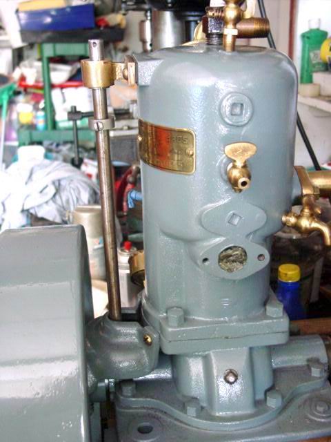
this is a 1913 Q1 that shows Searchers timer and the Trycock.
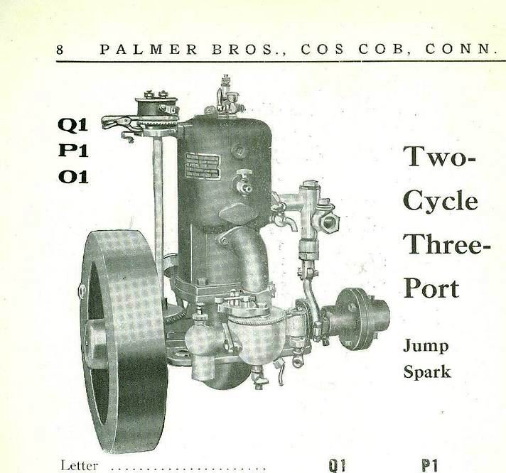
this is my 1914 Q1 some yrs back during restoration of a basket case.
** |
    
Richard A. Day Jr.
Senior Member
Username: richardday
Post Number: 804
Registered: 11-2003

| | Posted on Thursday, September 10, 2009 - 08:07 pm: | 


|
While I am reluctant to open the relief cock on a running engine with a lighted match present I wonder if it might allow the operator to check proper needle valve setting for max performance. Perhaps on a running 2 or more cylinder engine opening individual cylinder relief petcocks could show one cylinder is getting more or less fuel than the others. Just a thought. |
    
RichardDurgee
Senior Member
Username: richarddurgee
Post Number: 2174
Registered: 11-2001
| | Posted on Thursday, September 10, 2009 - 10:10 pm: | 


|
*
I'm sure that I am not the only one here that after getting very frustated with a balky flooded engine has taken the spark plug out and lit the cylinder to clear her out ! one time I remember the kids at school asking why I didn't have any eye brows and lashes, my mother asked the same question my dad a mechanic just looked at me and knowingly smiled ??
** |
    
Searcher
Senior Member
Username: searcher
Post Number: 333
Registered: 10-2004
| | Posted on Friday, September 11, 2009 - 12:33 am: | 


|
Here are photos of the primer cups on the Q2. Note the four sided wrench flats rather than the more common six sided flats. I associate the four sided configurations with the Imperial Brass Co. Note that the primer cups in the photogravures of the Q1 and Q2 Richard attached above also appear four sided. Given that, I am going to assume that these primer cups are original to the engine. Any ideas of how I'm going to restore the primer cup with the broken threads? If I try to silver solder the break back together, will the heat peel the nickel plating off? Would it be better to grind off all remnants of the threads and then solder a new threaded piece back on? Will heat destroy the integrity of the metal? What is the metal, it isn't brass?
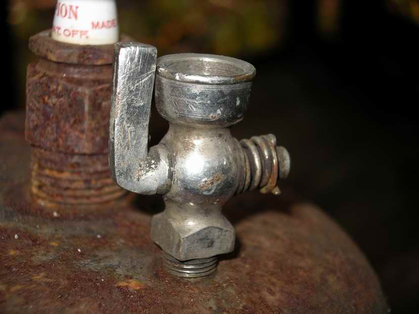
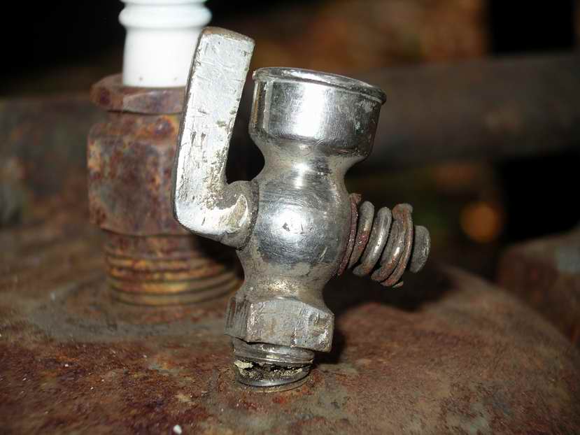 |
    
J.B. Castagnos
Senior Member
Username: jb_castagnos
Post Number: 469
Registered: 07-2002

| | Posted on Friday, September 11, 2009 - 08:22 am: | 


|
I would disassemble it and glue 4 pieces of key stock to the flats, chuck it in a 4 jaw on the lathe. Machine it even with the square section, counterbore it and machine a new nipple with a shoulder to fit. Silver solder it together. |
    
Searcher
Senior Member
Username: searcher
Post Number: 334
Registered: 10-2004
| | Posted on Friday, September 11, 2009 - 09:04 am: | 


|
JB,
Neat solution! Thanks. Will the heat from silver soldering take the nickel finish off? I don't suppose it matters, the priming cup isn't useful as it is.
I barely know one end of a lathe from the other but have had an interest in learning for some time. A friend loaned me an old 9" Southbend which has been sitting right here in my office awaiting attention for several months. I have had a stready stream of small jobs coming in and in this economy I take on all work that I can. This will be a very slow winter business wise
so I will try to learn how to run a lathe then.
Thanks again. |
    
J.B. Castagnos
Senior Member
Username: jb_castagnos
Post Number: 470
Registered: 07-2002

| | Posted on Friday, September 11, 2009 - 10:17 am: | 


|
Soft solder would probably hold if you have a large enough area, tin both sides and put it together, sweat it in. |
    
Ernie
Senior Member
Username: ernie
Post Number: 1034
Registered: 01-2002

| | Posted on Friday, September 11, 2009 - 10:53 am: | 


|
If you aren't going to paint the engine then a visable repair should be fine. Just silver solder it back together. Personally I am NOT into automotive like finish on old engines as MOST of them only had paint on cast iron. |
    
Robert
Senior Member
Username: robert
Post Number: 290
Registered: 07-2003
| | Posted on Friday, September 11, 2009 - 12:02 pm: | 


|
Another option would be to bend it back and soft solder the crack, then counter-bore (drill) up from the bottom, soft solder in a suitable piece of brass rod or tube, and redrill the hole as necessary. First remove the cone/plug from the cock of course, to prevent drilling into it by mistake.
If the wall of the threaded area is too thin, brass might not have enough strength, in which case a piece of stainless rod or tube might be a better choice.
My guess would be those are not original to the engine however. I think engine builders would have seated their plugs more deeply, which would only have required running the 1/8" NPT tap in a little deeper, being a tapered thread. Too easy to break off when sticking up that high, when the shoulder cannot give any support as it should.
Pretty sure I have a trycock(?) with the same handle as the broken one if you're stuck.
What a great find that engine is! Any story behind it? What does the second tag say? Thanks for posting the photos. |
    
Spence Kerrigan
Member
Username: kerrigan
Post Number: 19
Registered: 06-2008

| | Posted on Saturday, September 12, 2009 - 09:46 am: | 


|
J.B.Castagnos suggestion to chuck the valve and machine the broken end flat is good. Instead of soldering another piece to provide threads I would drill or bore the valve then tap the hole to allow installation of a close nipple of brass or stainless. Care must be exercised when screwing in the nipple so the valve does not crack. Use a good lubricating sealant and tighten until barley snug.
Removing the Dutchman from the cylinder is another problem. |
    
Robert
Senior Member
Username: robert
Post Number: 291
Registered: 07-2003
| | Posted on Saturday, September 12, 2009 - 10:51 am: | 


|
Threading instead of soldering would be a good idea on the inserted piece. Less chance of damaging the plating. Epoxy or solder would be needed to hold the new threaded part in place though, otherwise it would probably unscrew from the valve rather than the cylinder if you ever tried to take the cup out again.
Of course, the hard part is going to be getting it out of the cylinder in the first place! As it's 3/4 broken off already, that small 'hinge' holding the two pieces together could well break completely when you try to bend it back to vertical. A good bit of heat around it and then allow to cool, perhaps more than once, penetrating oil etc. I suspect solder would hold the two pieces together more strongly than epoxy when you attempt to unscrew it from the cylinder though. Wrap a sopping wet cloth around the valve above the break and use acetylene to give fast, high heat at the crack and you would probably get away without damaging the plating, except maybe around the crack. |
    
Roger DiRuscio
Senior Member
Username: solarrog
Post Number: 374
Registered: 03-2002

| | Posted on Saturday, September 12, 2009 - 12:54 pm: | 


|
That looks like a common primer cup, I would put it in my junk drawer and buy a matching set of Ebay. Silver solder is the only hope of saving this, and the finish will be damaged. Its most likely plated Brass/Bronze. Trying to repair this is an exercise of the mind for your own satisfaction. Its not economically feasible
Roger |
    
Spence Kerrigan
Member
Username: kerrigan
Post Number: 20
Registered: 06-2008

| | Posted on Saturday, September 12, 2009 - 02:19 pm: | 


|
I understand this primer cup is a rare antique. Locating one like it on eBay may be more difficult than finding the Holly Grail. The Dutchman is trash. Removing this little piece without damaging it will be as easy as removing a swallowed fish hook from a bass without injuring the fish. Break off the Cup. Get the Dutchman out somehow with without damaging the cylinder. Perhaps one of the more generous members of this group with machinist skills and equipment will volunteer to work on the cup. Looks like a 1/8, 1/4 or 3/8 IPS pipe thread. So a standard tap and close nipple should work, but check this out. If preserving the finish is a concern don't try solder. Knowing what material was used in manufacturing is important. At least learn if its magnetic. |
    
Searcher
Senior Member
Username: searcher
Post Number: 335
Registered: 10-2004
| | Posted on Saturday, September 12, 2009 - 05:43 pm: | 


|
In the past, I have posted quite a number of scans and photos on this site that were taken from old boating magazines but often there is no response. So, I am very pleased to get so many responses to my post of the Palmer Q2. I am learning quite a bit because of the responses – terms like trycock, Dutchman, and pant cuff protector are all new to me.
I assume a Dutchman is a broken off stud or nipple? As it turns out, both of the primer cups with their fragile nipples came out complete when coaxed with a lot of very light taps on a small wrench. Whew! Not often I get that lucky.
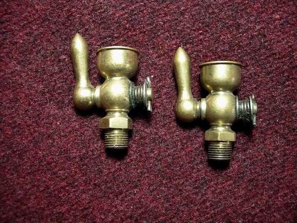
A response in this thread and an email indicate that the primer cups are probably not original. If I thought those nickeled primer cups were original, I would go to some length to preserve them. If they aren’t, then Roger is right, it would be an awful lot of effort to restore the damaged one and there would be no point. About five years ago, I bought a matched pair of new old stock primer cups (see photo below) that are very, very close to the one shown in the Q1 photogravure posted in this thread by Richard Durgee. Maybe I will use those instead since they seem more consistent with the original primer cups.
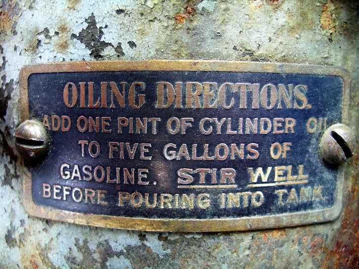
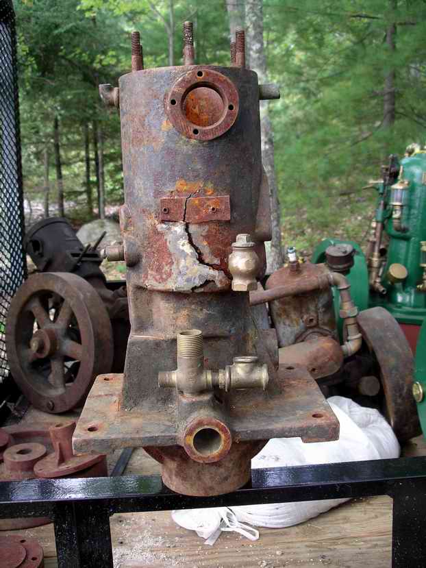
The other tag on the Q2 Robert asked about is the oiling instructions (see photo below). Robert also asked if there was a story behind this engine. Alas, I wish there was a real tale of adventure to go with it but the reality is much more mundane. I got it and three other engines from a fellow who bought them from an estate. The two Mianus engines in the package, one early and one late, had been almost totally dismantled many years ago. Apparently, the parts were scattered around the shed and he collected everything he could find in a couple of boxes. Both have salt damaged water jackets, one severe the other quite minor (see photo below). The fourth engine was a real small 2 hp pre 1907 Capital, Fifield Brothers, Augusta, Maine. What appears to be the original unmarked Holly carburetor for it was in one of the boxes of parts.
Robert, I looked through my meager supply of fittings for a trycock but there was nothing that resembled the one remaining on the engine. If you had a spare like that one, I would love to acquire it. Perhaps I could trade you one in another style for it.
Thanks to all of you that responded.
 |
    
Robert
Senior Member
Username: robert
Post Number: 292
Registered: 07-2003
| | Posted on Saturday, September 12, 2009 - 07:14 pm: | 


|
Sorry about the lack of responses - I must say I've been struck by the number of unanswered posts in the past. If we had a tab that would allow us to see the unanswered posts only, it might go some way to rectifying that.
I hope Andrew won't be offended if I say it might be time for a software upgrade??
I for one have certainly enjoyed the scans that you and Richard particularly - I hope I'm remembering correctly! - have posted so many of in the past.
I looked in my stock here, but no trycock/petcock with that handle here, but I will check my other location. I'm sure there is something like it there.
Those priming cups look perfect. I have one straight one with a similar handle, but those look exactly right.
Thanks for the provenance - might be worth getting into that shed yourself if it's not too late.
Am I right in thinking that oil mixing instruction plate is very unusual? There might be a market for reproductions since yours is so pristine. Dick, your comments on that? |
    
Richard A. Day Jr.
Senior Member
Username: richardday
Post Number: 805
Registered: 11-2003

| | Posted on Saturday, September 12, 2009 - 07:42 pm: | 


|
Don't have a clue what the potential market might be. Just keep in mind the began to appear in late 1910 early 1911, so don't put them on engines which are not already drilled and tapped for them.
Will be off the air for about a week so don't think I am "Toes UP" |
    
Ernie
Senior Member
Username: ernie
Post Number: 1037
Registered: 01-2002

| | Posted on Saturday, September 12, 2009 - 09:40 pm: | 


|
I'm confused...
What is with the trycock stuff. I have read this post several times and don't see it mentioned. I guess I must be going blind.
"Trycock" is a steam term. However... All petcocks used under a lot of pressure especially constant pressure can NOT have a spring on the tapered valve. So my thoughts are the term "trycock" has been used to diferentiate from the usual gas engine petcock with a spring on the tapered valve vs one with out a spring as used on a boiler to check the actual water level.
thoughts???
As to the nickle plated priming cups I don't remember any of the original Palmer engines that I have seen with any nickle plating. Not saying they didn't just I have yet to see a documentated original one with nickle plating. |
    
Searcher
Senior Member
Username: searcher
Post Number: 336
Registered: 10-2004
| | Posted on Saturday, September 12, 2009 - 10:29 pm: | 


|
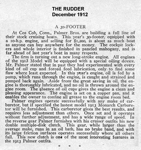
I may have posted this article before. Nevertheless, it provides some references that may help in dating changes Palmer made to their engines.
 |
    
RichardDurgee
Senior Member
Username: richarddurgee
Post Number: 2177
Registered: 11-2001
| | Posted on Sunday, September 13, 2009 - 10:00 am: | 


|
*
Ernie I caused the confusion about the Trycock discussion. Dick Day and I were posting replys to searchers Palmer Model Q and then started a separate email discussion on dating the model Qs, I sent Dick a photo of an older engine and he replied that the 'Trycocks" were missing (the relief petcocks on the side of the cylinders) and he remembered a brief discussion in a pre 1900 palmer catalog that explained their use.
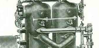
Dick then found the info and posted it above. Very interested in this and wanting to share it here I posted this ---
Dick, I am fascinated by your post above, I have been aware of these relief valves directly into the cylinder and have thought of them as a way to unflood an engine or as a compresion release to turn engine over to prime it etc, but I admit I hadn't thought of opening and striking a match to see the color of the combustion mixture !
Also new to my nomenclature in gas engines is the Trycock, I have referred to these as relief valves or petcocks ? looking up definitions in old machinery book- a Trycock is a valve or faucet that indicates the PRESENCE or LEVEL of a fluid or gas-- a Petcock is a faucet or valve that controls the FLOW of a fluid or gas !
I thank you for bringing this up and consider it a lesson well learned .
----
It had no reference to the nickel plated broken
primer cup on top of Searchers engine !
Hope this helps clarify not mystify ??
** |
    
Lawrence T Wolfe
Senior Member
Username: larry_from_maryland
Post Number: 379
Registered: 07-2003

| | Posted on Sunday, September 13, 2009 - 02:58 pm: | 


|
Dick don't forget your mud shoes. I went to the mason dixon show in westminester yesterday and it was wet and rainy. looks like sunday is the only day i can make arcadia. |
    
Searcher
Senior Member
Username: searcher
Post Number: 337
Registered: 10-2004
| | Posted on Monday, September 14, 2009 - 07:57 pm: | 


|
In a previous message in this section, I mentioned I had acquired the Palmer along with three other engines and a couple of boxes of parts. This oiler, stamped Hall Manufacturing, New York, was in one of the boxes. I thought it might have gone with the older of the two Mianus engines but I don't see any place for it. Also, I did not see anything like it festooning the Mianus engines in the few magazines I have of the period. Is it marine or automotive or steam?
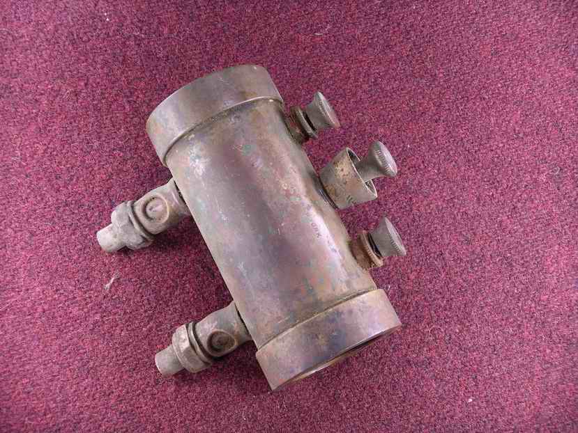
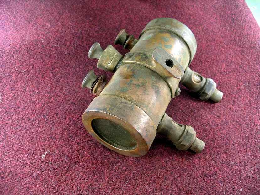 |
    
Robert
Senior Member
Username: robert
Post Number: 298
Registered: 07-2003
| | Posted on Friday, September 18, 2009 - 09:25 pm: | 


|
Here's what I've got for "trycocks", three are 1/4 NPT and one is 1/8 NPT. Not a perfect match for your other one. If you take some closeups and perhaps try an ad on Smokstak, you'll probably find one identical to yours.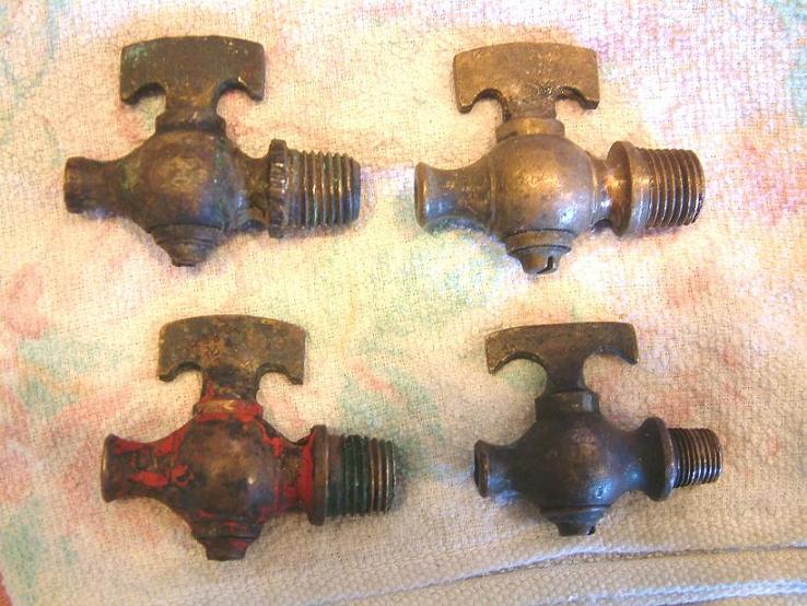 |
    
RichardDurgee
Senior Member
Username: richarddurgee
Post Number: 2184
Registered: 11-2001
| | Posted on Saturday, September 19, 2009 - 05:24 pm: | 


|
*
1908
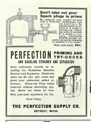
** |
    
Searcher
Senior Member
Username: searcher
Post Number: 340
Registered: 10-2004
| | Posted on Saturday, September 19, 2009 - 08:49 pm: | 


|
Robert,
Thanks for digging out your selection of try cocks. I have some time before I will get to the Palmer. As you have surmised, I would like to find a perfect match. I have never tried advertising on Smokstak, in fact I probably haven't been to that site more than two or three times in the past. Worth a shot.
Again, thanks for looking. |
    
Scott Noseworthy
Senior Member
Username: scott_n
Post Number: 112
Registered: 02-2008
| | Posted on Tuesday, September 22, 2009 - 04:40 pm: | 


|
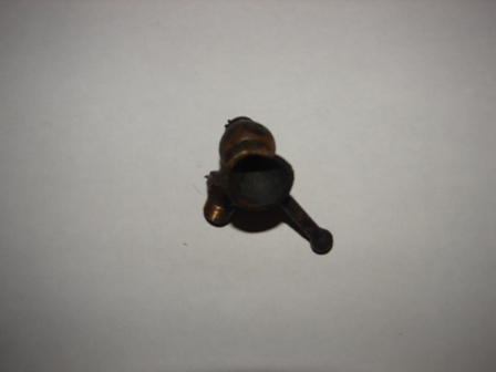
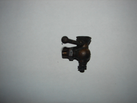
this palmer has the right primmer cups and compression relese thay came off a 1916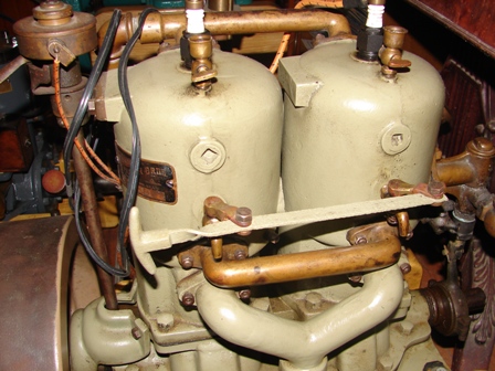 |
    
Scott Noseworthy
Senior Member
Username: scott_n
Post Number: 113
Registered: 02-2008
| | Posted on Tuesday, September 22, 2009 - 04:50 pm: | 


|
And this primmer cup also is a compression relese it has three difarint spots you can set it primmer cup up compression relese down or shut so it may be a trycock and it is spring loded
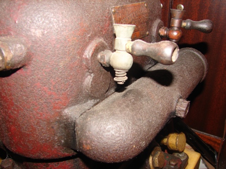 |
    
Scott Noseworthy
Senior Member
Username: scott_n
Post Number: 114
Registered: 02-2008
| | Posted on Tuesday, September 22, 2009 - 04:59 pm: | 


|
hear is a nother one
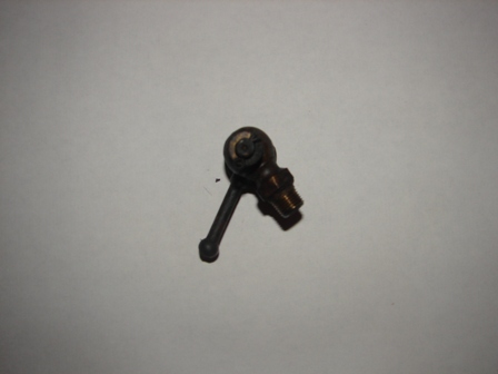
 |
    
Ernie
Senior Member
Username: ernie
Post Number: 1050
Registered: 01-2002

| | Posted on Tuesday, September 22, 2009 - 07:25 pm: | 


|
Scott,
You are correct on the compression release valves as being original.
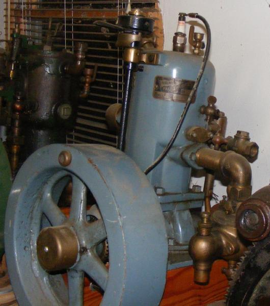
However Palmer used priming cups with an (L) shaped handle.
As an example here is a pic of my NOS Q1. I got it from the son of the gentleman that worked at Palmer. He brought it home in pieces. The priming cup is original. The compression release and carb are not. I have no idea as to actual year as it has no serial number. However it is a late engine as the water pump has 3 bolts, the plug is in the top, the timer is steel, it has the oil mix ratio tag and the hole for an oiler is not drilled.
Hope this helps
Ernie
 |
    
Ernie
Senior Member
Username: ernie
Post Number: 1051
Registered: 01-2002

| | Posted on Tuesday, September 22, 2009 - 07:34 pm: | 


|
Searcher,
When you get around to the Palmer give me a hollar. I most likely have the priming cups you need. Some sort of a trade will most likely work.
Ernie |
    
Searcher
Senior Member
Username: searcher
Post Number: 342
Registered: 10-2004
| | Posted on Wednesday, September 23, 2009 - 12:15 am: | 


|
Ernie,
When the time comes, I will contact you. Thanks.
Scott, thanks for posting the photos.
I have done considerable research on the Knox engine produced by Camden Anchor Rockland Machine in Rockland and later in Camden, Maine. In the early days, they used Powell Signal oil cups, later they used Sherwoods, Lunkenheimer Paragons, and Wilkinsons. I expect they used Lavignes at some point and Americans as well as other brands. The grease cups they used also included Sherwood and Lunkenheimer. It quickly became evident that they bought oil and grease cups from whoever offered the best deal at any given moment in time. I suspect the same was true with Palmer. Consequently, I would find it impossible to fault anyone restoring their engines using any of the available brands of oil and grease cups as long as they were of the same period as the engine. |
    
Richard A. Day Jr.
Senior Member
Username: richardday
Post Number: 808
Registered: 11-2003

| | Posted on Wednesday, September 23, 2009 - 08:19 pm: | 


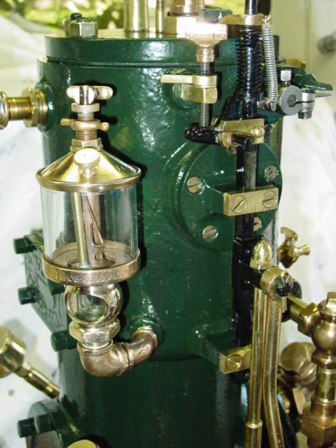
|
I was very surprised to find out that Palmer Bros.made their own lubricators for some period. Ernie has one and I have one. Suspect they quickly got out of that business as there were a lot of steam people providing oil cups in mass production. I wonder if there are any other Palmer lubricators out there??? |
    
RichardDurgee
Senior Member
Username: richarddurgee
Post Number: 2189
Registered: 11-2001
| | Posted on Wednesday, September 23, 2009 - 08:31 pm: | 


|
*
Palmer oiler on Model C.
** |
    
Searcher
Senior Member
Username: searcher
Post Number: 343
Registered: 10-2004
| | Posted on Wednesday, September 23, 2009 - 09:35 pm: | 


|
Here are two more Palmer oil cups, one a cylinder oiler (has the by pass tube) and the other a journal oiler.
I don't think Palmer actually made these. Rather, I think Palmer had these made for them by Sherwood Brass.
Note that these are both nickel plated.
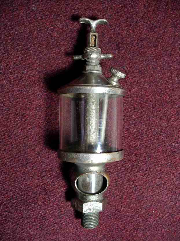
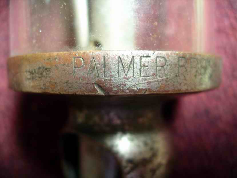
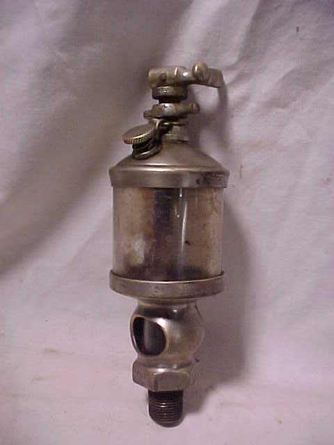 |
    
Richard A. Day Jr.
Senior Member
Username: richardday
Post Number: 809
Registered: 11-2003

| | Posted on Thursday, September 24, 2009 - 09:33 am: | 


|
Richard it is amazing how OME turns up evidence every day it seems which seems to turn upside down what we thought yesterday. I wonder if nickel plated trim was offered at an extra charge. I have never seen it mentioned in any of the catalogs I have. Perhaps they were only used on show engines for crowd pleasers! Wonder if we will ever know. Nice looking MOdel C. I agree with Ernie let the casting surface show. I have no evidence they used fillers and polished the surfaces of the engines. |
    
Spence Kerrigan
Member
Username: kerrigan
Post Number: 22
Registered: 06-2008

| | Posted on Thursday, September 24, 2009 - 09:52 am: | 


|
How can nickel plate be distinguished from chrome plate on an object? I know nickel is sometimes used under chrome but was not aware that nickel was commonly used as the final finish. |
    
Ernie
Senior Member
Username: ernie
Post Number: 1052
Registered: 01-2002

| | Posted on Thursday, September 24, 2009 - 03:14 pm: | 


|
From what I have seen nickel wears off like the oiler pics Dick posted above they look like a thin coat of paint. Chrome peels off in flakes like old paint.
Ernie |
    
Scott Noseworthy
Senior Member
Username: scott_n
Post Number: 115
Registered: 02-2008
| | Posted on Thursday, September 24, 2009 - 04:59 pm: | 


|
Nickel came along first and if done right looks like it hase a beter luster to it and like Ernie sed you can tell nickel by the way it wears off dont know when thay started to use crome |
    
RichardDurgee
Senior Member
Username: richarddurgee
Post Number: 2190
Registered: 11-2001
| | Posted on Thursday, September 24, 2009 - 05:44 pm: | 


|
*
Dick, It is truly the age of information, These computers that we have a love- hate- confused relationship with allow us to compile and access info on an umbrella view that we with localized info never had available. Your question above " I wonder if nickel plated trim was offered at an extra charge" ? I have not consciously recorded that specific info into my Old marine Eng data base but I typed in "NICKEL" in the comments section and these names popped up offering nickel plated brass !
1. Mohawk
2. Wolverine
3. Barber
4. Tuttle
5. Baker a heretofore unmentioned or listed eng Co in Quincey, Mass that in 1905 only offered their engs brass nickel plated !
6. Maximotor engs in 1913 had polished aluminum cases and nickel steel open valve mechanisms and push rods ?
some mfgrs advertised that besides the option to Nickel plate that you could also have a custom eng tag made with your name on it ??
there was a few mfgrs that boasted that they filled their castings and hand sanded them to a smooth finish and then enameled in high gloss ?
I find Info about finishing and paint colors very hard to come by with most old marine eng ads and catalogs in black and white .
** |
    
Ernie
Senior Member
Username: ernie
Post Number: 1053
Registered: 01-2002

| | Posted on Thursday, September 24, 2009 - 05:55 pm: | 


|
Richard,
Add Thrall and all of the Thrall family to your list as having a salt water option. All brass enven the carb was nickel plated.
Here is a pic of mine from one of the Thrall threads
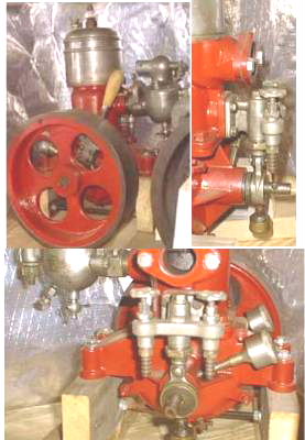 |
    
Ernie
Senior Member
Username: ernie
Post Number: 1835
Registered: 01-2002

| | Posted on Saturday, June 07, 2014 - 06:17 pm: | 


|
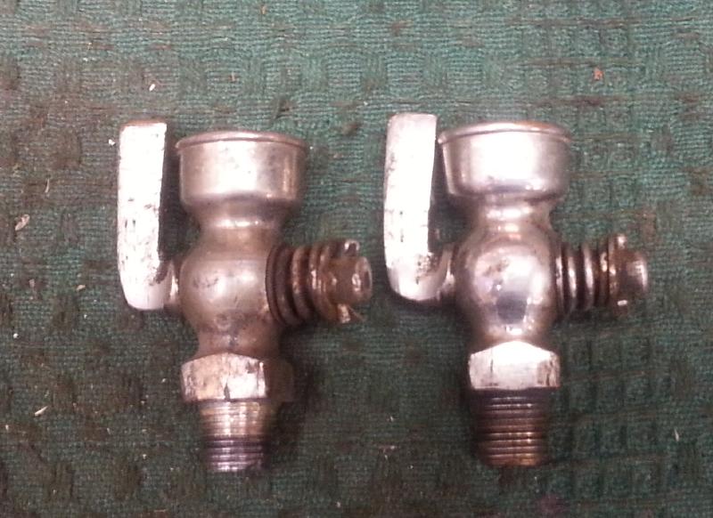
I ended up with the Q2 at the beginning of this thread.
Did the JB repair suggestion but used silver solder.
They are now both back in the engine so it is as found.
The repaired Priming Cup is on the left. Nickel seems fine after the heat.
 |
    
J.B. Castagnos
Senior Member
Username: jb_castagnos
Post Number: 925
Registered: 07-2002

| | Posted on Sunday, June 08, 2014 - 07:16 am: | 


|
Nice repair Ernie. |


